Chapter 10: Direct Current Circuits
10.0. Overview
We're going to continue our study of circuits that have charges moving through them (current I), and in particular, how current and potential change in more complex circuits.
We're also going to look at some real-life applications of these circuits.
Let's get started!
- EMF & Terminal Voltage
- Resistors in Series, Parallel
- Kirchhoff's Rules
- Galvanometers, Ammeters, Voltmeters
- RC Circuits
10.1. EMF & Terminal Voltage
We've talked briefly about the potential difference that forms across the terminals of a battery—a 9 Volt battery typically has a potential difference of 9.0 Volts, for example. Things are a little more complicated than that, however.
If you use a voltmeter to measure the potential across those terminals when the battery is providing energy to a circuit, the measurement is a bit less than that, say (in this example) 8.7 Volts. This is due to something called the internal resistance of the battery.
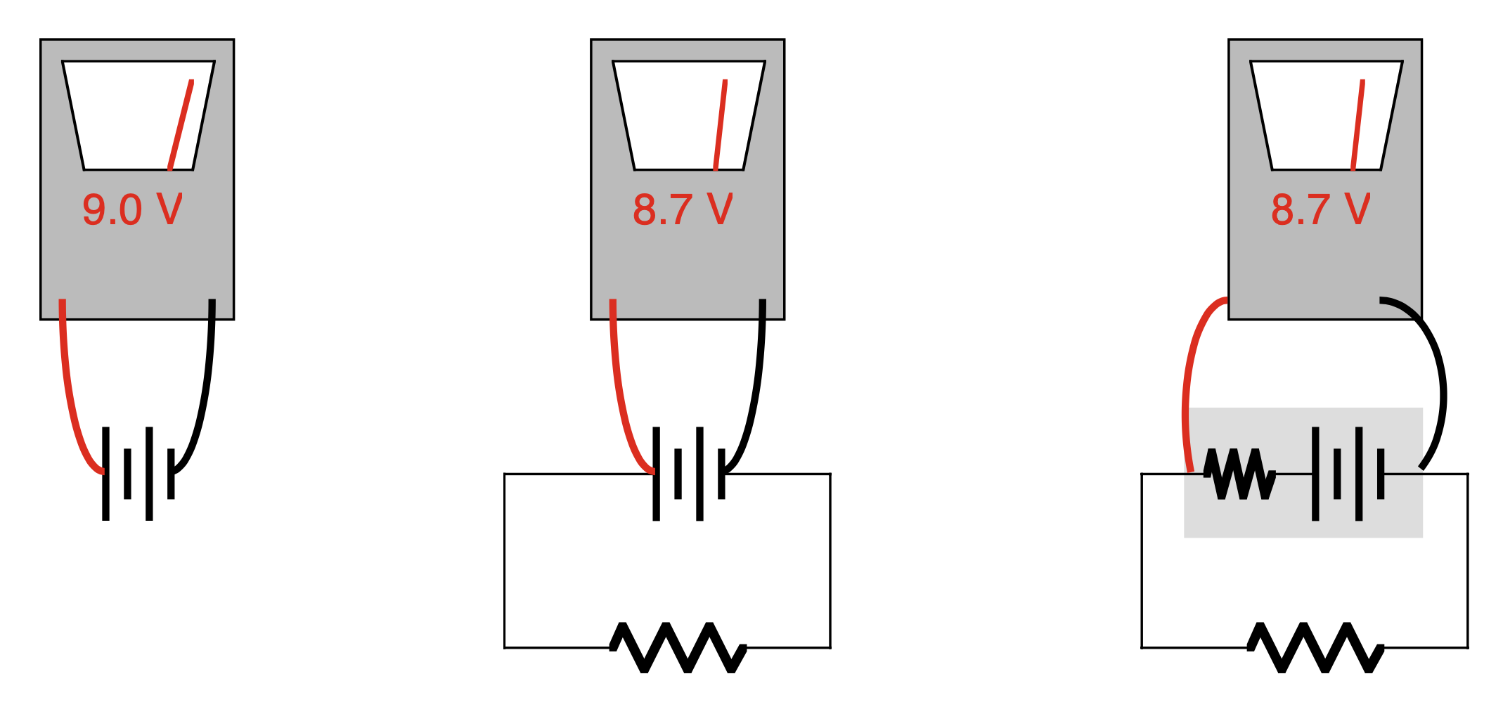
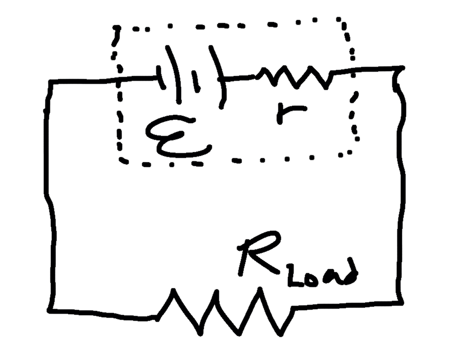
Internal resistance
Batteries provide an "open-circuit" potential difference that is referred to as emf (for "electromotive force"), indicated by the symbol ε.
When the emf source is delivering current into a circuit, however, the actual potential difference across the terminals is somewhat less, due to an "internal resistance" in the device, which is related to how difficult it is for the battery to actively produce energy while operating a circuit. This reduced potential is called the terminal voltage, and can be determined using the formula

The internal resistance is usually indicated by a lowercase r, while the actual resistance of the circuit (sometimes called the "load resistance") is indicated with an uppercase R.
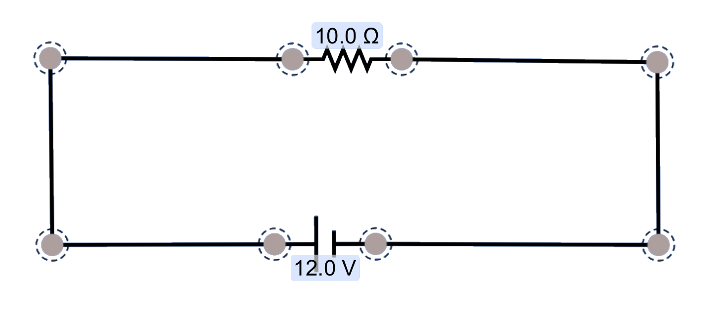
Calculating internal resistance
A battery with an emf of 9.0 V is connected to a load resistance of 100 Ω, with a resulting measured terminal voltage of 8.7 V.
- Draw and label a picture of the circuit, including the internal resistance
- Identify the current running through the circuit.
- Identify the internal resistance in the battery.
- 0.087 A
- 3.4 ohms
Internal resistance is an interesting aspect of electrical circuits, but it's not something that we pay attention to in every problem. You may see problems that refer to the voltage of a battery V or the emf of a battery ε. For this course, in most cases, these terms—"emf", "potential difference", and "voltage"—are used interchangeably; internal resistance is considered to be negligible in our work.
Unless otherwise indicated, of course.
10.2. Resisters in Series, Parallel
We've already looked at capacitors in simple circuits, and how they can be used to store charge. Let's look at the behavior of resistors in a circuit, and how they influence current and electrical potential differences.
10.2.1. Resistors in Series
If you consider a simple resistor circuit in terms of the Water Analogy, the resistance in a circuit is analogous to a clog in a pipe: something is inhibiting the flow of material (either water or charges).
If we place additional resistance in line ("in series"), we introduce additional clogs in the system which further restrict the flow. If we increase the amount of restriction by a factor of 2, there is a decrease in the current by a factor of 2.
Resistors in Series
For resistors placed in series in a circuit, the equivalent resistance of all the resistors can be calculated as

The current I is the same through all resistors in the branch, but the potential difference across each resistor varies as a function of the resistance, where ΔV = IR.
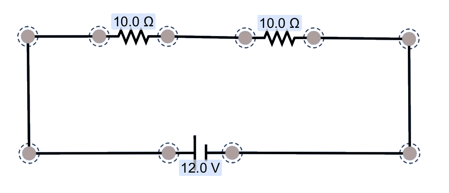
Resistors in series
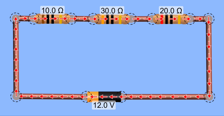
Calculate the equivalent resistance for these resistors, the current throughout the circuit, and the potential changes over each device in this circuit. Also, calculate the Power produced by the battery and the power dissipated by each resistor.
The equivalent resistance is the sum of the resistances, or 60Ω. The current through the entire circuit is I = V/R = 12V/60Ω = 0.20 Amps. The potential changes over each device can be calculated using V = IR. For the first resistor, V = IR = (0.20)(10Ω) = 2.0 Volts. For the second resistor, V = (0.2)(30) = 6.0 Volts. For the third resistor, Δ V = 4.0 Volts.
Note that the total decrease in potential for these resistors matches the total increase in potential supplied by the battery.
To calculate the Power for the battery, use P = IV. For the resistors, it's easier to use P = I2R.
10.2.2. Resistors in Parallel
It is also possible to connect resistors in parallel, their ends attached so that charges travel through two or more branches simultaneously. Let's explore that in detail, using a series of animations.
In this first example, we're seeing conventional current move through a resistor. Take a moment to determine what the current in Amps is for this situation.
Here, we've placed a second resistor in parallel with the first. Although we are including a second resistor to the circuit, which might lead one to believe that the overall resistance has increased, what we've also done is created a second path for charges to flow through. Even though that charge is traveling through a resistor, its doing so via a pathway that didn't exist before.
The battery continues to supply the same potential difference, but because we have a new branch of the circuit, the overall resistance is less than it was when we just had a single resistor. With a smaller equivalent resistance, the battery is able to push more current through the circuit.
You should be able to see in the animation that the charges are moving more quickly through one of the resistors than the other.
Resistors in Parallel
For resistors connected in parallel in a circuit, the equivalent resistance of all the resistors can be calculated as

The potential difference ΔV is the same across all resistors in the branch, but the current through each resistor varies as a function of the resistance, where I = ΔV/R.
Add yet another resistor in parallel, and we again have a smaller overall resistance, and therefore increased current coming out of the battery, supplying charge to all three branches in the circuit.
Take a moment to consider the relative amounts of current coming from the battery and going through each resistor. Does this animation correctly model current through those resistors? Does the higher resistance have less current than the lower resistance does?
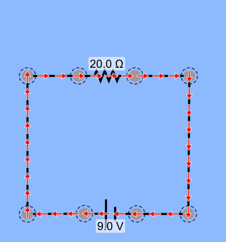
Resistors in parallel
Calculate the equivalent resistance for these resistors, the potential change over the resistors, and the current at each branch in the circuit. Also, calculate the Power produced by the battery and the power dissipated by each resistor.
First, let's calculate the equivalent resistance for these three resistors.

Notice that this value is less than the resistance of any single resistor in the circuit, because of all the extra branches that were opened up for charge to flow through.
The potential change over the resistors we can identify as being the same as the potential of the battery: 12.0 V
Now that we've identified the potential difference over the resistors we can get the current through each of them, as well as the overall current from the battery.

Notice that the total current passing through all the resistors matches the total current coming from the battery, as we'd expect.
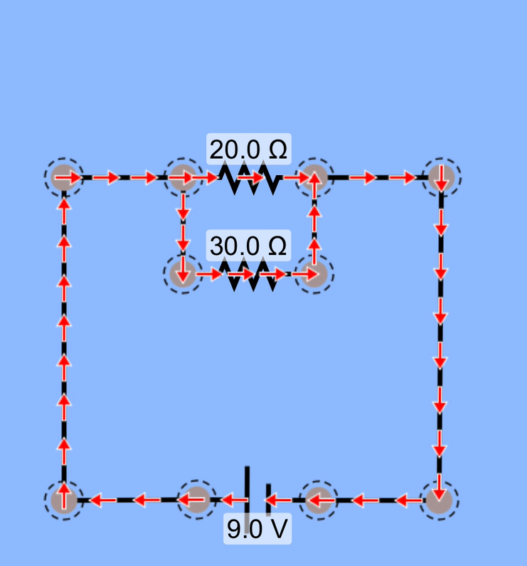
Slightly more complex
Analyze this circuit to determine everything you can about it.
The strategy here is to simplify the two parallel resistors into a single, equivalent resistor. Create a new diagram and the two resistors are now in series, and then can be simplified into a single equivalent resistor. Solve for current and potential difference, and use that information to back your way out of the simplifications.
10.3. Kirchhoff's Rules

Some circuits can't be simplified using the analyses we've used to this points. For these more complex arrangements we can often use Kirchhoff's Rules.
There are two Kirchhoff's Rules, and a strategy for applying them to circuits.
Kirchhoff's Junction Rule
The Junction Rule states that "the total current traveling into a node (a connecting point for 3 or more wires) = the total current coming out of the node." This rule is based on conservation of charge: you can't have more charge traveling into a node than is leaving.


The Junction equation for the first junction on the left would be I2 = I1 + I3.
What are the junction rules for the other two junctions?
I1 = I2 + I3
0 = I1 + I2 + I3
The third junction isn't possible, of course—clearly, at least one of our currents is pointing in the incorrect direction. Still, we can use this equation to identify the correct currents and their directions, as you'll see below.
Kirchhoff's Loop Rule
The Loop Rule states that "the sum of the potential changes around a closed loop must equal zero." This rule is based on conservation of energy. Energy that is introduced into a loop must be dissipated in that loop.


To apply the Loop Rule, pick a location in the loop to start (I often pick the negative end of a battery, if the is one), and begin tracing in the direction of presumed current and tracking potential changes. Keep on going until you return to where you started.
For the circuit on the left here, trace across the battery, which increases the potential (and thus a + V for the equation), then continue on to the resistor, which we know decreases potential, which gives us a -ΔV, or (by Ohm's Law) -IR. The sum of these changes is 0.
Thus, the Loop equation for the first loop on the left, assuming the current is traveling in the direction indicated, would be:

What are the loop equations for the other two circuits?


NOTE: It may be that in tracing a loop, you find yourself traveling in the opposite direction of the current flow. In this case, tracing over a battery will involve decreasing the potential V (because you're moving from the battery's high potential to its low potential), and tracing over a resistor will involve an increase in potential (because resistors typically decrease potential, but you're tracing in the opposite direction).
You'll get used to it!
Using Kirchhoff's Rules
To use Kirchhoff's Rules to analyze a circuit:
- On the circuit diagram, identify and label a current (I1, for example) and a direction of flow (indicated with an arrow) for each separate branch of the circuit.
- Write out a series of Node equations using Kirchhoff’s Junction Rule. (Make sure you don’t duplicate any equations.)
- Write out a series of Loop equations using Kirchhoff’s Loop Rule. (The total number of Junction and Loop equations = the number of unknown current branches you’re solving for.)
- Solve these simultaneous equations.
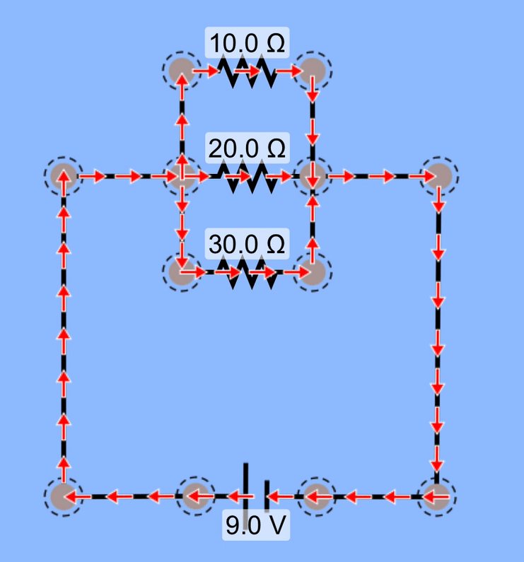
First Kirchhoff's Problem
Examine the circuit here, and identify the currents in each branch, as well as the potential changes over each component (batteries and resistors) in the circuit. Also, how much power is dissipated by the 2Ω resistor?
This is going to be fun!
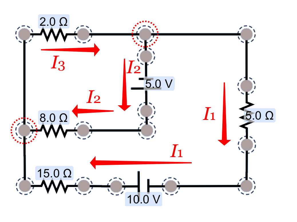
First we'll need to identify each branch in the circuit, give it a current label, and indicate a presumed direction for the current. It doesn't matter if we get the direction wrong: our result will reveal the correct direction.
For this example, I'm going to label the branches as shown here, with these directions.
With these three currents identified, I can see that we need three simultaneous equations to be able to solve for those three values. How can I go about identifying those three equations?
First, I'll identify the nodes—the points at which three or more wires are connected, highlighted by dashed circles in the diagram—and write a non-redundant equation for them using the Kircchhoff's junction (node) rule. For the upper node, that equation is:

We could also write an equation for the bottom node, but that equation would be redundant; it's identical to the equation we just wrote down, and doesn't yield any new information. To find two more equation for our three-unknowns problem, we'll need to do to some loop-rule analyses.
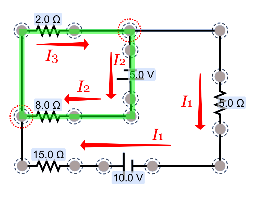
I can see that there are three possible loops to choose from, highlighted in green in each of these diagrams. Which ones should we use for our two additional equations?
Let's use this first one here. We'll need to decide which direction we want to trace the loop, in the clockwise direction or the counterclockwise direction. To start things out easy, I'm going to trace through in the clockwise direction, which also happens to be in the same direction as the current directions I've selected.

Note what we did with the signs here:
- If we're tracing along a current in the direction of charge flow, a battery increases the potential in the circuit—it adds energy to the circuit—so it's an addition (+) change.
- If we're tracing along a current in the direction of charge flow, a resistor decreases the potential in the circuit—it dissipates energy from the circuit—so it's a subtraction (-) change.
We'll have more to say on the signs of these changes in a minute.
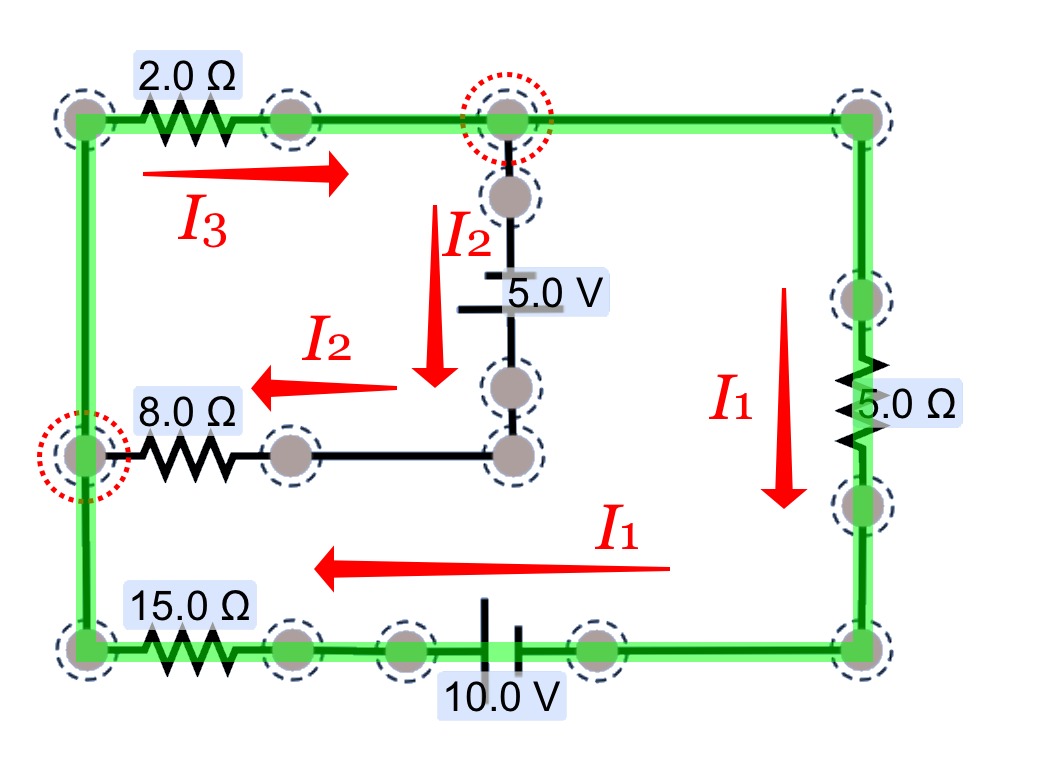
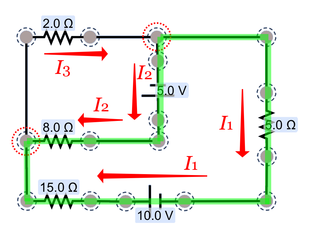
It's possible to trace through this second loop to get the third equation we need, but let's skip this one and proceed to the last loop for our analysis. That will allow us to learn a few important details about applying the loop rule.
I'm choosing to trace through in a counter-clockwise direction, starting from the top node. (It doesn't matter where you start from and it doesn't matter which direction you trace.) The voltage changes for this loop will be:

Note that there were some challenges in this one!
- If we're tracing along a branch in the opposite direction of the battery, we subtract the voltage—the + end of a battery is at a higher potential than the - end, so we're tracing across a negative potential change.
- If we're tracing in along a branch in the opposite direction of the current, we're tracing from the low-potential end of the resistor to the high-potential end; we're following an increase in potential, which is identified by adding that potential change in our loop-rule equation.
We now have three simultaneous equations that we can use to solve for each for each of the current magnitudes and directions in our problem.
10.4. Galvanometers, Ammeters, Voltmeters
There are three types of meters that are commonly used in analyzing electric and electronic circuits, and they are all typically contained within a single device, the multimeter.
A switch is used to select which measurement one wishes to make—current or voltage—and that switch brings into play a variety of components that allow for making the correct measurement. Digital multimeters are available to do the same thing... but what are the principles involved in these meters?
10.4.1. The Galvanometer
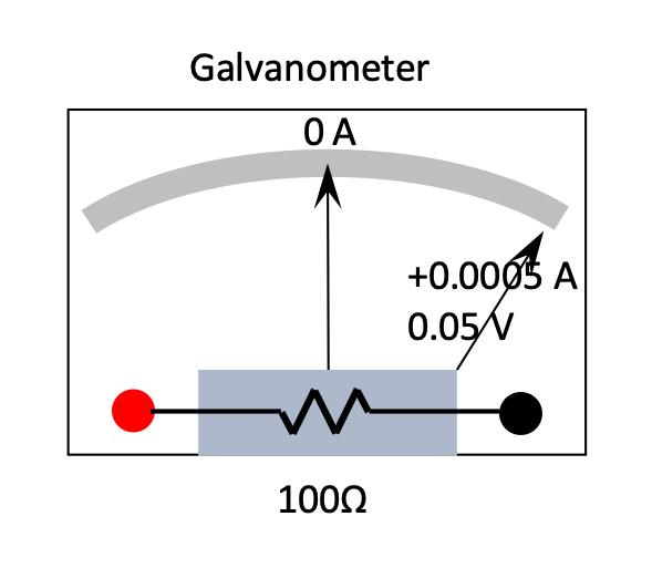
A galvanometer is a type of meter that, in conjunction with appropriate resistors, will allow one to measure current (as an ammeter) and electric potential difference (as a voltmeter).
The typical needle-based galvanometer has a coil of wire with some known resistance (100 Ω is common), with a spring mechanism that allows the needle to deflect left or right across the face of the meter at a known current value of 5.0×10⁻⁴ A.
Thus, a current of 0.0005 A through the coils would cause the meter to deflect from 0 to a full reading of 0.0005 A (either to the left or the right, depending on the direction of current flow). A potential difference of (V = IR) 0.05 Volts would produce this full deflection.
10.4.2. The Ammeter
If you'd like to measure more current than the 0.001 A that the galvanometer can handle, we have to add some circuitry to the galvanometer so that it will still work. What if, for example, we want to be able to have it fully-deflect at 0.100 A?
Definition: Ammeter
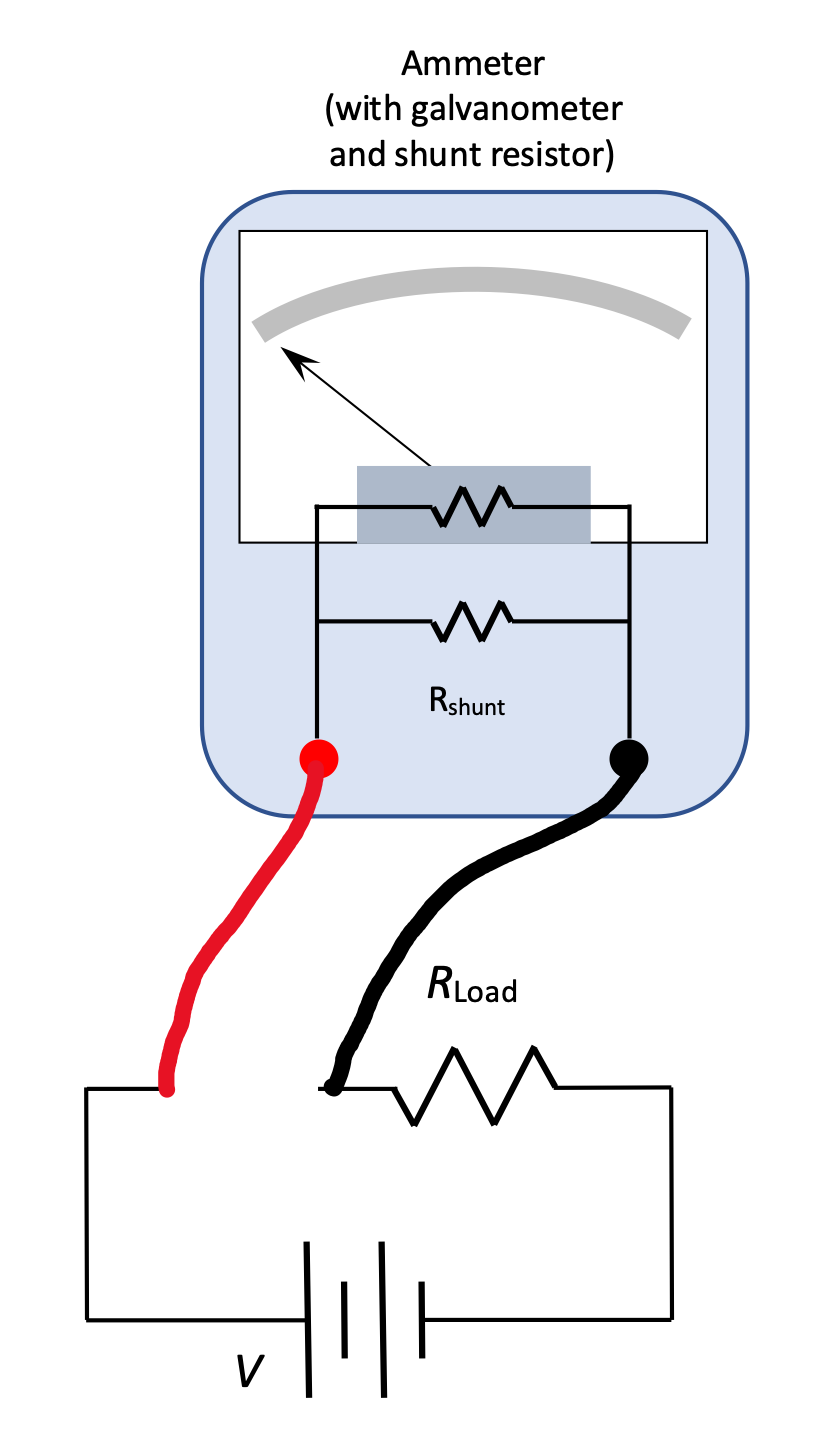
An ammeter uses a galvanometer and a shunt resistor to be able to measure other currents. We know that a voltage of 0.05 Volts across the terminals of a galvanometer produces full deflection. So:

10.4.3. The Voltmeter
If you'd like to measure more voltage than the 0.05 Volts that the galvanometer can handle, we have to use a different strategy. How can we alter this galvanometer so that it will be able to measure voltages (deflect fully) up to 10V?
Definition: Voltmeter
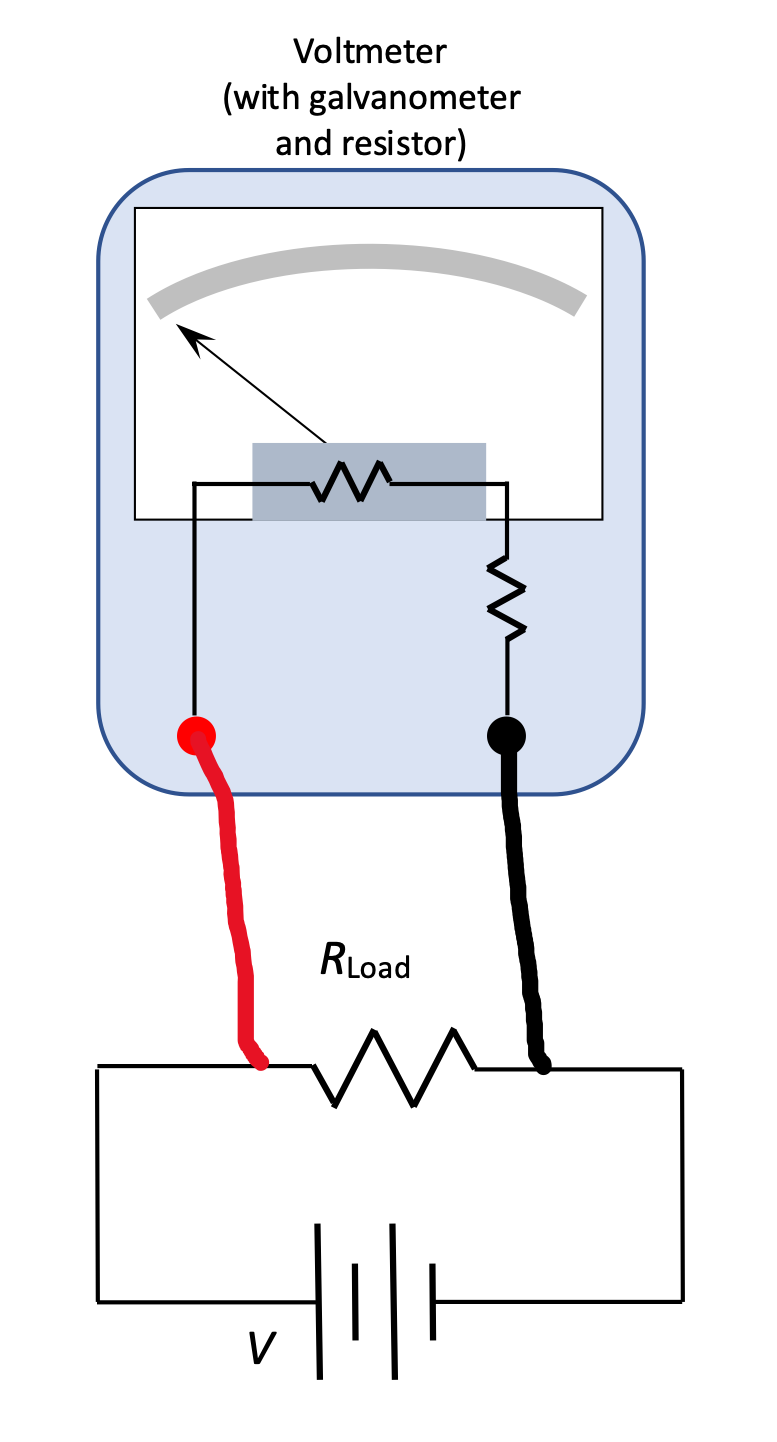
A voltmeter uses a galvanometer and a supplementary resistor to be able to measure other voltages. We know that a current of 0.001 Amps across the terminals of a galvanometer produces full deflection. So:

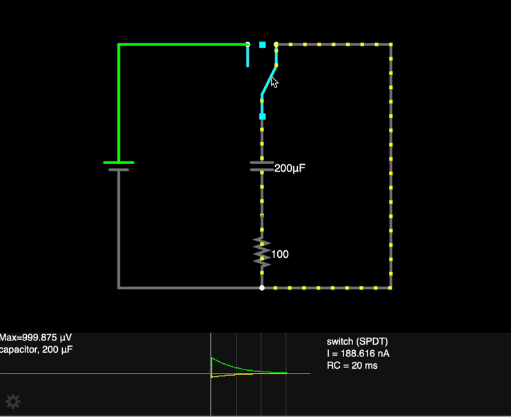
10.5. RC Circuits
A circuit with a resistor and a capacitor placed in series is called an RC Circuit, and they exhibit an interesting time-dependent behavior. Let's look at both a qualitative and quantitative analysis.

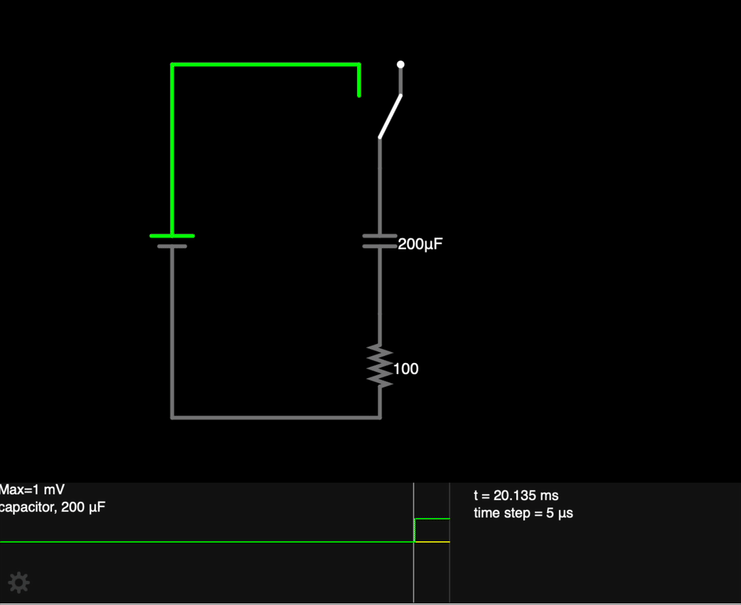
RC Circuits, qualitative description
When the switch S is closed at time t = 0:
- The capacitor C has no charge built up on the plates yet, so the potential difference across its plates is 0.
- As current flows in the circuit (inhibited somewhat by the resistor), charge accumulates on the plates, and a potential difference builds up "in opposition" to the flow of charge.
- Charge continues to build on the capacitor plates until Vcap = Vbattery, at which time current stops flowing.
We can also understand the behavior of this circuit more quantitatively.
RC Circuits, quantitative description
We begin the analysis by considering the potential changes in the circuit.

Now that we've solved for dq/dt, bring the terms with q to the left side, and split dt to the right in anticipation of integrating:

Integrate the left side with respect to charge q, and the right side with respect to time t:

We've solved for charge q on the plates of the capacitor as a function of time.
When t = 0, e0 = 1 and the charge q on the plates is 0. After a long period of time has passed, ea large negative number approaches 0, and q approaches the maximum charge on the plates, Qmax = CV0.
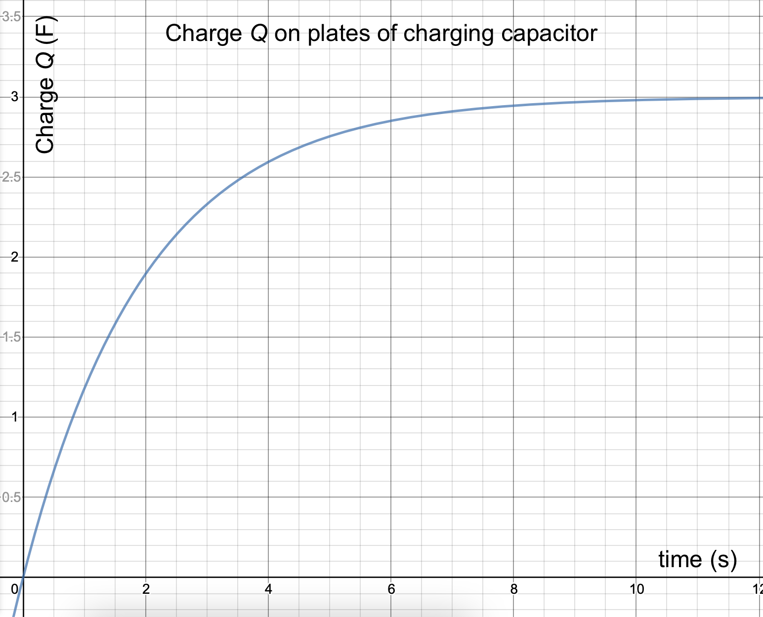
10.5.1. Time Constants, and charging capacitors
This is an important equation:

The quantity RC is called the "time constant" for the circuit, and indicated with the Greek letter "tau" (τ).

In this circuit, τ represents the amount of time in seconds for the charge to reach 0.632 of its total value.
Analyzing an RC circuit
An RC circuit has a 6.0 V battery, a 200 μF capacitor, and a 5000Ω resistor.
- Draw a picture of the circuit.
- What is the charge on the plates, q0, just after the switch is thrown?
- What is the time constant for the circuit?
- How much charge is on the plates 3 seconds after the switch has been thrown?
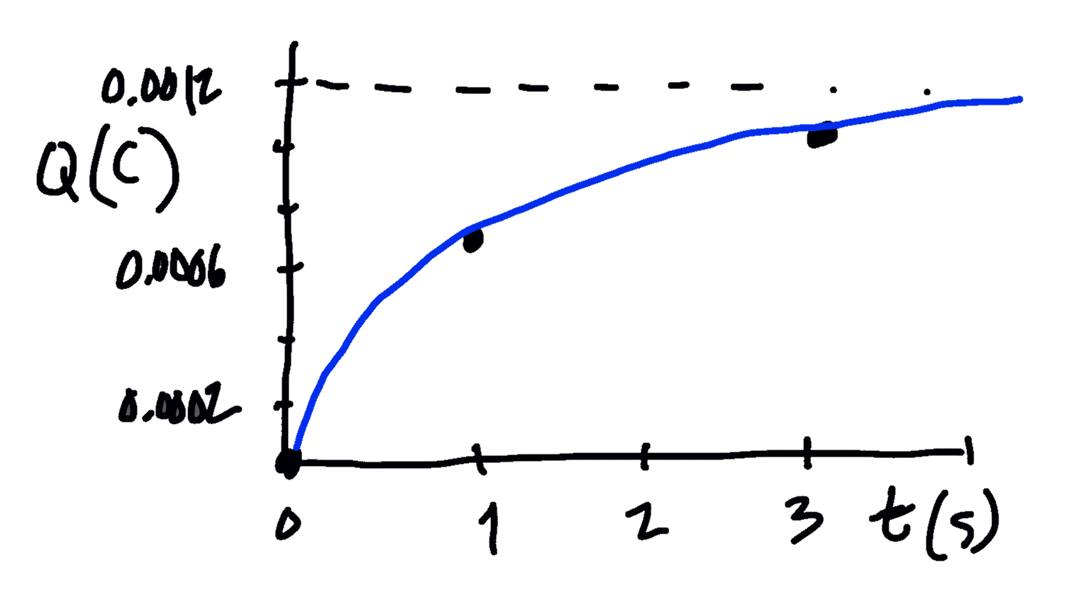
- Sketch a graph of the circuit's charge vs. time, using at least 3 data points that you calculate.
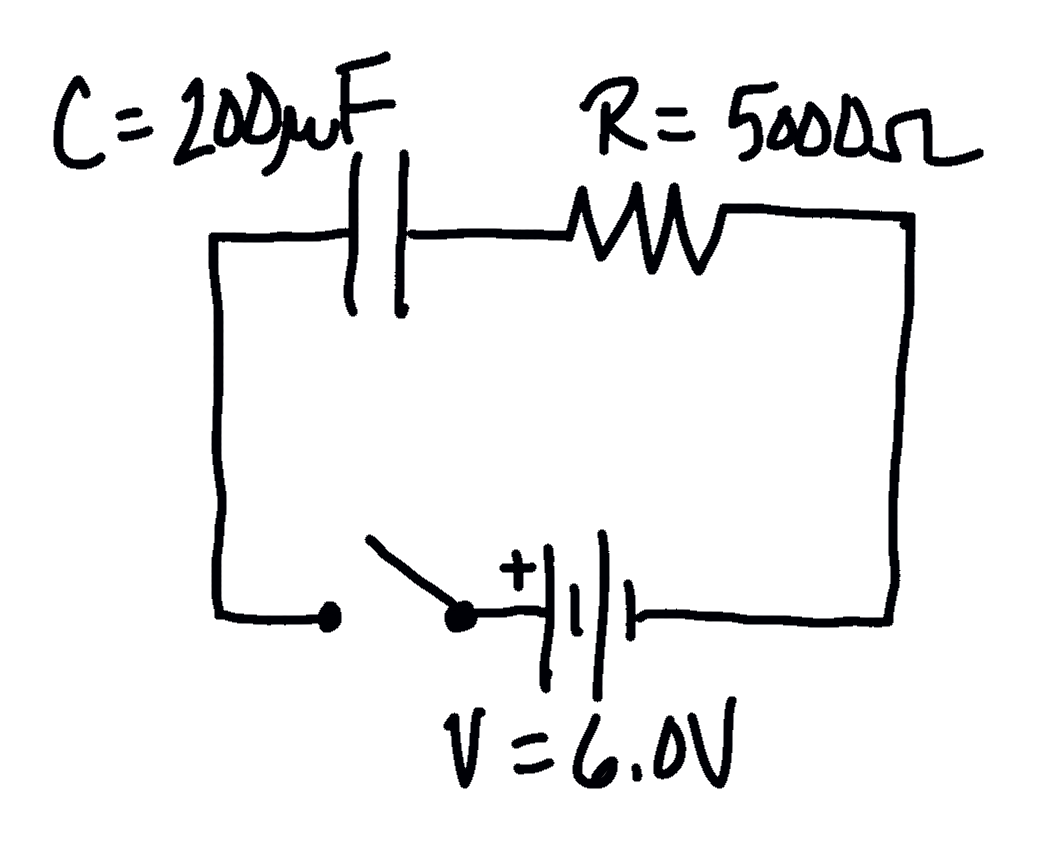
- There is no charge deposited on the plates yet. Solving the charge equation with a time t = 0 confirms this.
- The time constant is τ = RC, so τ = (5000 Ω)(200e-6 F) = 1.0 seconds.
- Solve the equation with a time constant of 1.0 seconds and t = 3.0 seconds:

- Three data points? The easy data points are q = 0 at t = 0, q = 0.632 of the maximum Q, which occurs at one time constant (1 second), and one more, say at three time-constants (t = 3 seconds, which I just calculated above), and then draw a curve to match those points.
Now that we know how charge Q varies over time, can we determine how the current I varies over times as well?
RC Circuit, current I over time for a charging capacitor
We've already determined the charge being deposited on the plates over time, as

Let's take the time-derivative of that charge to identify how the current is changing over time:

We can see the current diminishing as the charge on the plates of the capacitor builds up, creating a greater and greater potential difference to counter the potential difference provided by the battery. After "a long period of time" has passed, current drops to 0.
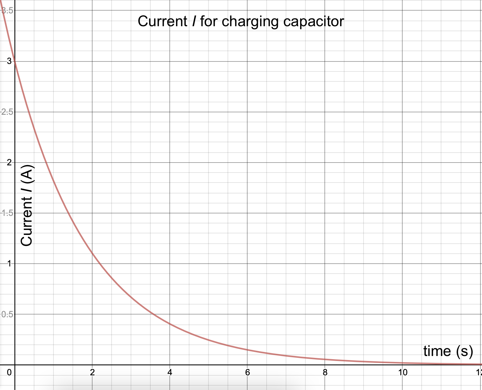
Analyzing current in a charging capacitor
Examine the graph of I vs. t for the RC circuit shown above.
- What is Imax for this circuit?
- What is the value of I after one time-constant has passed? What fraction of the initial Imax does this represent?
- What is the time-constant for this circuit?
- Examining the RC circuit more closely you see that the color bands on the resistor are White-Black-Red-Gold. What approximate resistance does the resistor have?
- What approximate capacitance does the capacitor is this circuit have?/li>
- According to the graph, at time t = 0, I = 3.0 Amps.
- The time constant occurs when t = RC, or when the exponent on e is -1. At one-time constant, then, e-1 = 0.36787944117144233... So, when does I = 0.368 of Imax? 0.368 of 3.0 A = 1.1 A.
- According to the graph, that current occurs looks like about 2.0 seconds, so τ = 2.0 seconds.
- White-Black-Red-Gold = 90 ×102 = 9000 Ω, +/- 5%.
- τ = RC, so C = τ / R = 2.0 s / 9000 = 2.22 × 10⁻⁴ F, or 222 μF.
10.5.2. Discharging a capacitor
Once a capacitor has been charged up, it can be removed or disconnected from the battery, and the charge will remain on the plates—capacitors can store charge for a long time. If the two plates of the capacitor are subsequently connected by a conductor, charges will move through the conductor until there is not longer a potential on the plates.
Let's examine this process more closely.
RC Circuit, charge on a discharging capacitor

We assume that the switch S has been moved to the left for a long period of time, so that the capacitor has completely charge up (Q = CV0).
- The switch is moved to the right, disconnecting the battery from the circuit, and forming a closed circuit loop with the capacitor and the resistor.
- Charges flow from the capacitor as current (inhibited somewhat by the resistor). The initial current I0 from the capacitor is based on the potential difference (the "push") from the fully charged capacitor.
- As charge drains from the plates, the potential difference across the plates decreases, resulting in a decreasing current as well.
- After a long period of time, all net charge will have been removed from the plates of the capacitor. The energy that was stored in the capacitor has been dissipated as heat through the resistor.
How can we describe the charge on the plates q over time?
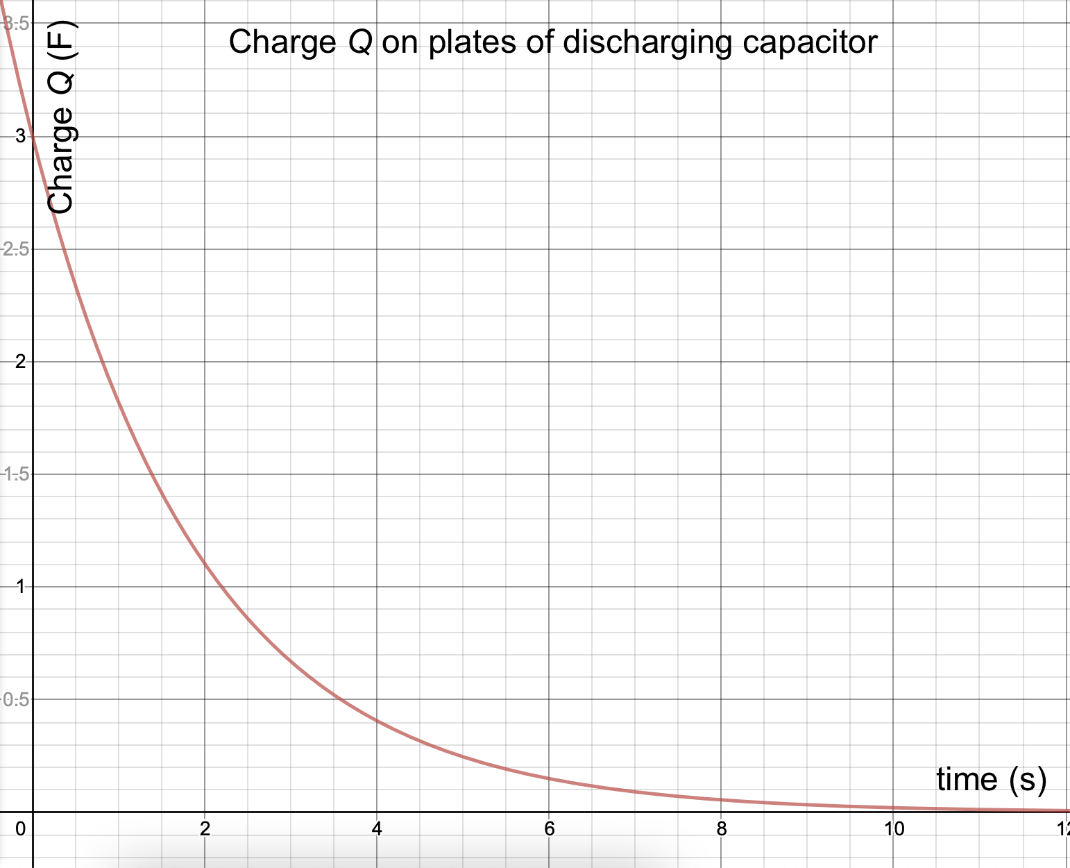
Let's use the same type of analysis that we used for charging the capacitor: set up a Loop Rule equation for the potential changes in the electric circuit. Now there are just two elements in the circuit: the resistor and the capacitor.

RC Circuit, current for a discharging capacitor
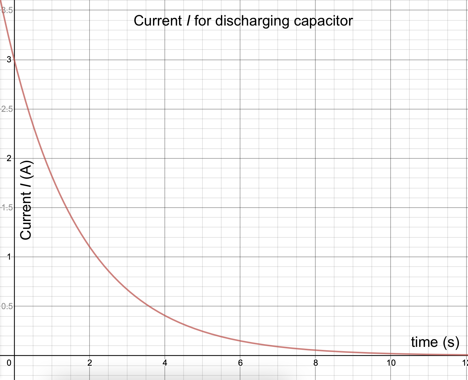
As you might expect from our previous analysis, the current from the discharging capacitor begins with a maximum value of:

This current drops off over time as the charge on the plates decreases. By taking the time derivative of the Q equation above we can determine that

(The negative sign in this equation refers to the fact that the charge on the plates is decreasing over time.)
10.5.3. Understanding circuits
Solving some circuit problems relies not on a step-by-step analysis but on being able to apply an understanding of how the components work under various conditions.
Thinking through a circuit

In this circuit the switch S is closed at time t = 0.
- Calculate the current I0 in the resistor R2 immediately after the switch is closed.
- Calculate the current I in the resistor R1 a long time after the switch is closed.
- A long time after the switch is closed, how much Power is being dissipated by resistor R2?
- A long time after the switch is closed, how much energy is stored in the capacitor?
- When the switch is first thrown, there is no charge built up on the plates of the capacitor, and thus no potential to oppose the flow of charge. Thus, this branch of the circuit is effectively a conductor that "short circuits" resistor R1. Thought of this way, the current is I = V/R2.
- A long time after the switch is closed, the capacitor has built up charge on its plates so that current can no longer flow through that branch. All of the current is traveling through R1 and R2. Thus, the current is I = V/(R1 + R2).
- We can calculate Power with a few different formulae. Because we already know I and R, let's calculate using P = I2R.
P = I2R
P = [V/(R1 + R2)]2 × R - Energy stored in the capacitor can be calculated using U = (1/2)CV2. We know C, but what's the potential V across the plates of the capacitor?
It's the same ΔV as across the resistor R1, because those two are connected in parallel. So...
VC = VR = IR = (VR1) / (R1 + R2)
UC = (1/2) C [ (VR1) / (R1 + R2) ]2