Chapter 8: Capacitance
Before we get started with our next topic, let's review what we've covered to this point in the course:
- Electric Forces
Charges exert forces on each other, like charges repel, opposites attract - Electric Fields
Exist in the presence of charged particles, apply forces to other charges - Gauss's Law
Used to determine electric field in certain symmetric situations - Electric Potential Energy
Measure of how much work it takes to move charges through electric fields - Electric Potential
Measure of how much energy per unit charge it takes to move through fields


8.0. Overview
In the next unit, we'll conclude our study of electrostatics by learning about capacitance. Following that, we'll finally get to look at moving charges (current), and direct current (DC) circuits, one of the most practical aspects of our work this semester.
Let's get started!
- Definition of Capacitance
- Calculating the Capacitance of a System
- Batteries, Capacitors in Series and Parallel
- Energy in a Capacitor
- Dielectrics
8.1. Definition of Capacitance
Before we define capacitance, let's take a look a look at what happens when a battery (which produces a potential difference) is connected to parallel conducting plates.
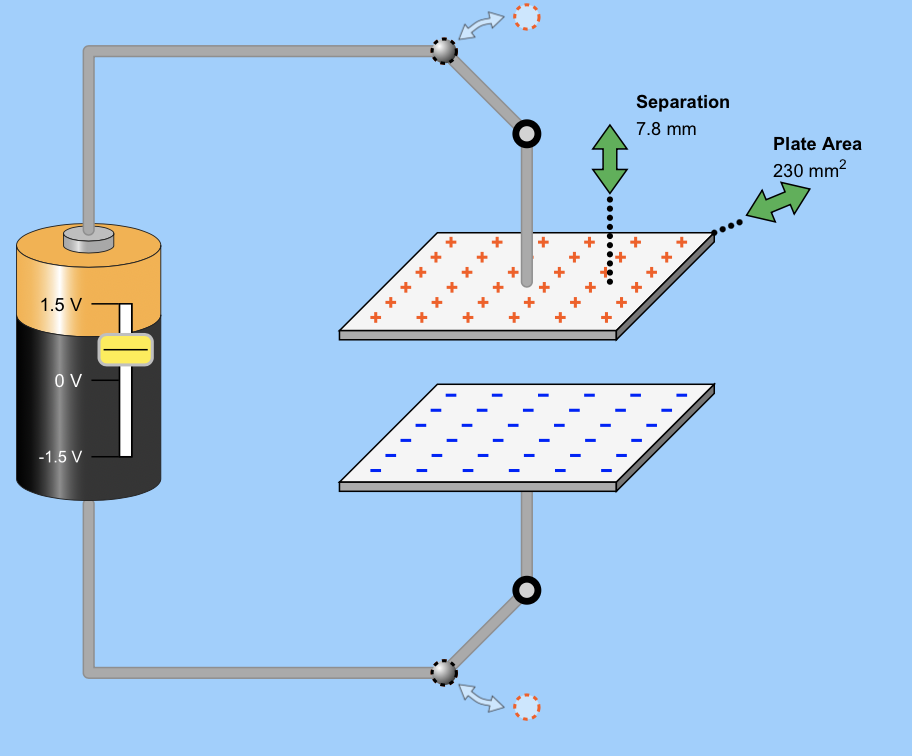
In this example, the battery provides a potential difference that pushes charges onto the plates of the capacitor. The amount of charge that can be stored on the conducting plates varies depending on a number of factors, including the potential difference in the battery, the area of the plates, and how close they are together.
Definition: Capacitance
The capacitance of a conductor (or conductors) is a measure of the conductors' ability to store charge.
By definition:

Capacitance is always positive, and is a measure of how much charge can be stored on a conductor at a given electric potential.
Calculating capacitance
What is the capacitance of this system, where each conductor has a charge of +/- 3 Coulombs, and a 9.0 Volt potential difference exists between the two conductors?

Calculating capacitance
Two conducting plates have a charge of 1.2 mC on each, with a 6.00 V potential difference between the two of them. What is the capacitance of this system?

8.2. Calculating the Theoretical Capacitance of a System
We may not know the charge and potential of a capacitor, but we can still calculate its theoretical capacitance with a simple strategy:
- Assume a charge of magnitude Q
- Calculate the potential V of the system (using techniques from last chapter)
- Use C=Q/V to determine the capacitance
Let's see how to apply this strategy.
Calculating capacitance for an isolated conductor
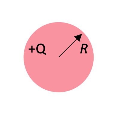
Calculate the capacitance of an isolated conductor with a charge +Q and a radius R.
The sphere has the ability to store charge on it, and by supplying a potential—a push on the charges—we can transfer a given quantify of them onto the sphere. How much charge we can put on the sphere ultimately depends on how big the potential is.
The capacitance is calculated using the formula:

It makes sense that the capacitance—the ability to store charge on the spherical conductor—varies linearly with radius. The bigger the radius of the sphere, the more charges we can crowd onto its surface.
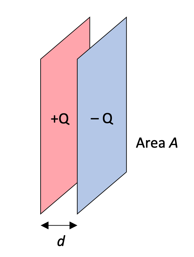
Calculating capacitance for parallel plates
Consider two parallel conducting plates, each with area A, separated by a distance d and with equal and opposite charges on them. Assume that plates are close together compared to their area so that we can neglect the edge effects and assume that the electric field E is constant between them. Calculate the capacitance of this system.
Solving this problem requires knowing about the potential differences between parallel plates, and knowing about the electrical field between those plates.

This is an important formula, as can be seen by the fact that it's on your equation sheet for this course. ;)
Calculating capacitance for a cylindrical capacitor
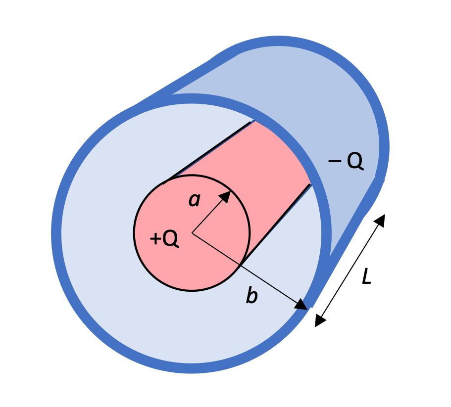
A cylindrical conductor of radius a and charge +Q is coaxial with a larger cylindrical conducting shell of radius b and charge -Q. Find the linear capacitance of the system C/L .
In applying the integral  , keep in mind that E is a vector with a direction
  . It helps to keep the signs straight if we integrate in the direction of that vector, ie, in the direction of the electric field.
So, with positive away from the center (because the inner cylinder has a positive charge with field lines radiating away from it:

Regardless of which plate is at high potential, we calculate the capacitance of the conductors (always reported as a positive value) as C = Q/ΔV:

Note that the longer the capacitor, the more room we'll have to store charge on it, increasing its capacitance.
Calculating capacitance for a spherical capacitor
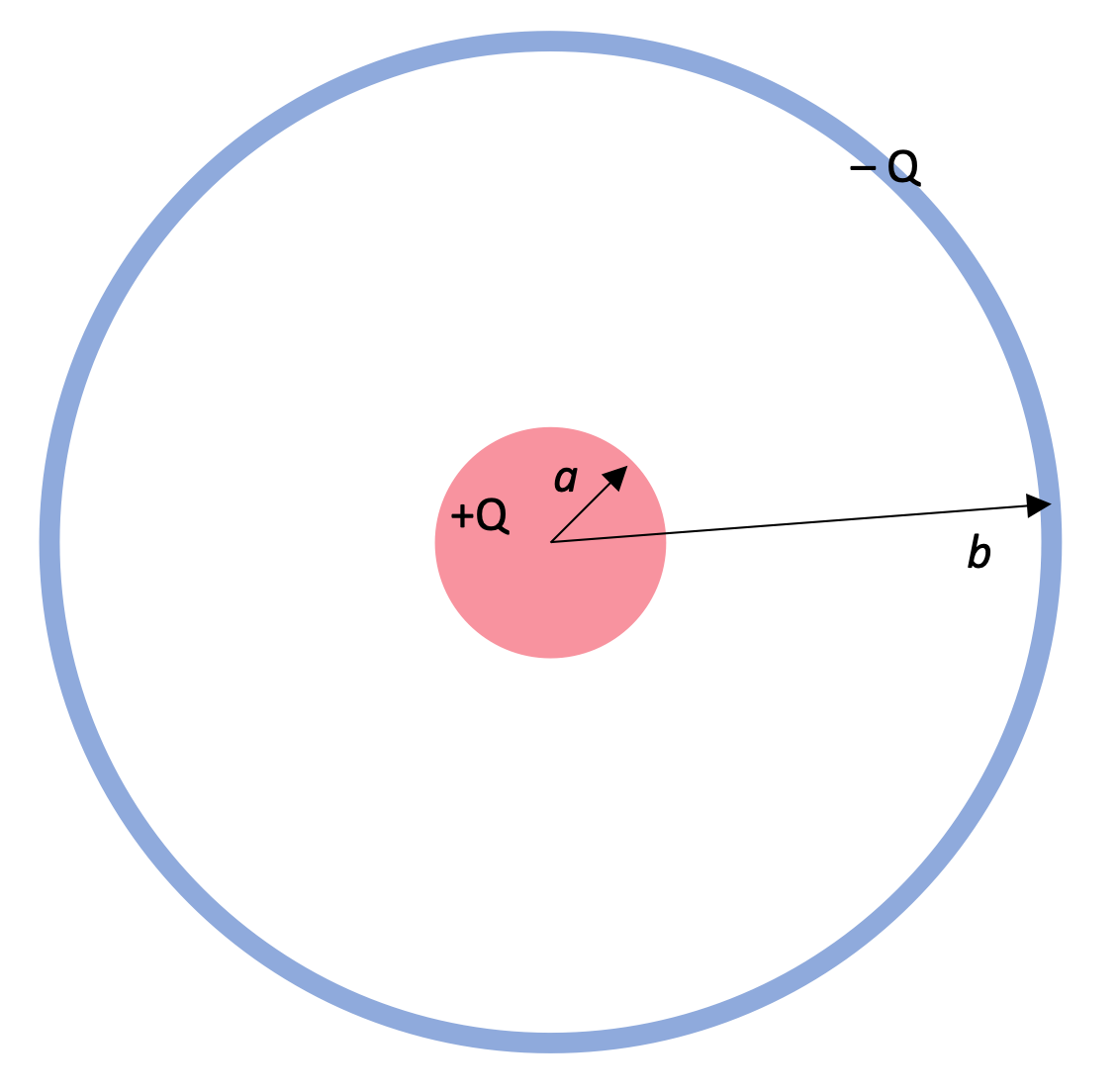
Determine the capacitance of a spherical capacitor, with an inner sphere of radius a charged to +Q, and an outer sphere of radius b charged to -Q.
We'll choose to integrate in the direction of electric field, from high potential, at radius a, to low potential at b. By setting up the integral this way, the field E and dr will be oriented in the same direction, and the dot-product (cos θ) will be cos θ = 1.

Use Gauss's Law to determine that

Evaluate the interval to get:

Substitute into the equation for capacitance to get:

8.3. Batteries, Capacitors in Series and Parallel
8.3.1. Batteries, a source of potential difference

We've been talking about pushing charges onto the conductors of a capacitor by using a potential difference, and one of the common ways of creating that potential difference is by using a battery, in which a chemical reaction causes positive and negative charges to accumulate in two separate locations.
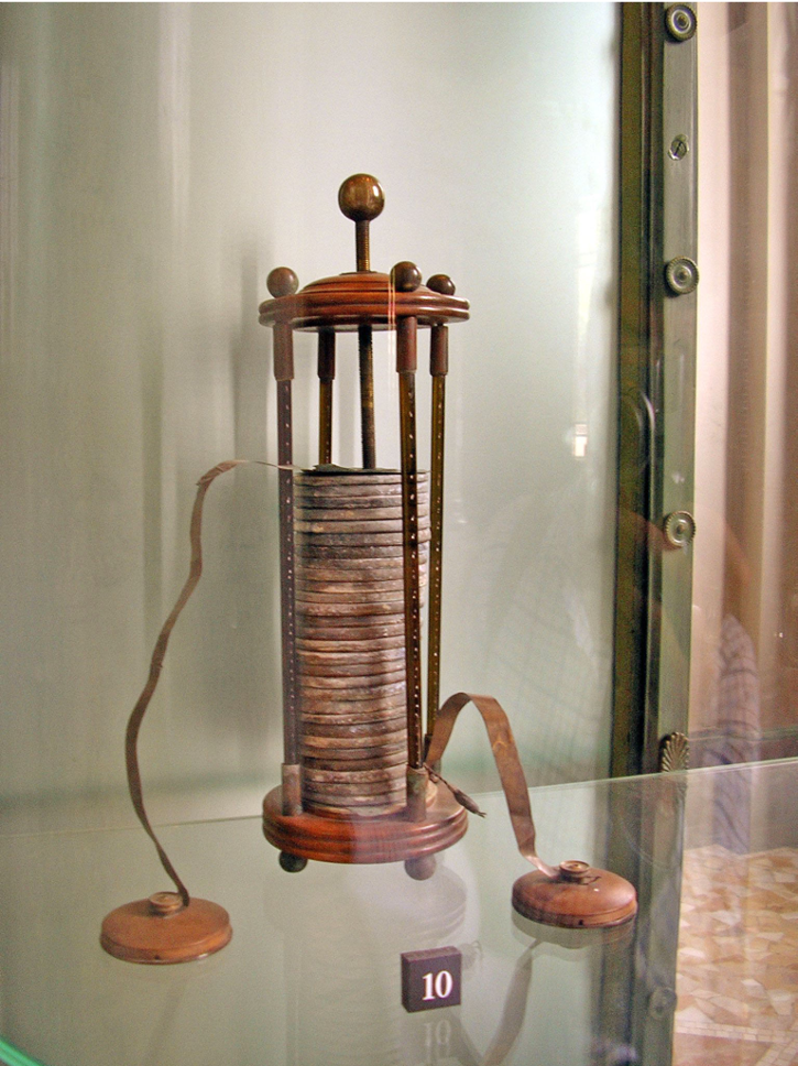
The discovery that simple chemical reactions can have this effect is primarily attributed to Alessandro Volta who performed a series of experiments in the 1780s. Volta determined that two different metals, separated by a corrosive (acid or alkali), would create a small electric current, and furthermore, that the effect could be increased by sandwiching the metals/corrosive in a "voltaic pile."
Let's see how the chemical process in a modern battery actually works.
How a Battery works
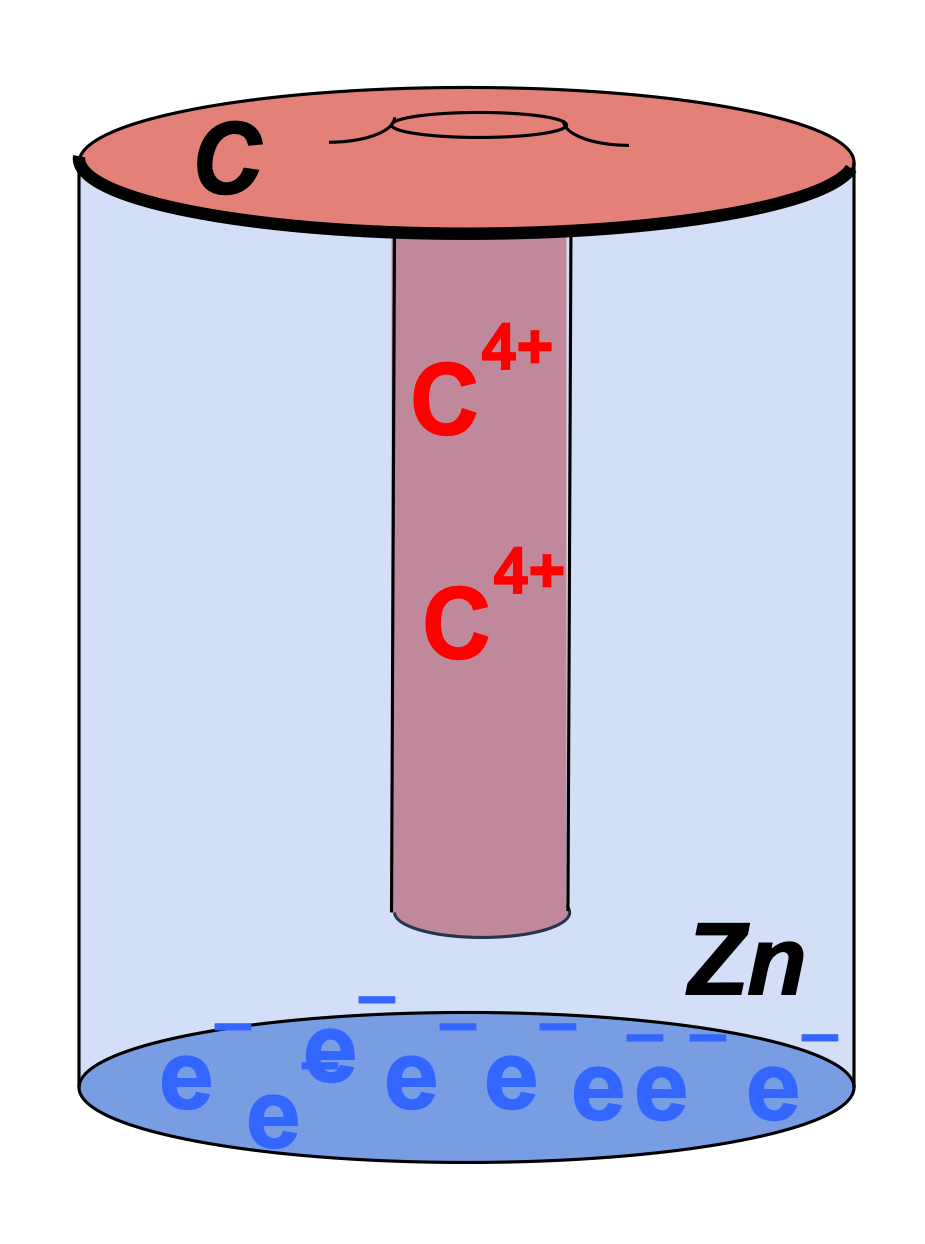
As the acid eats into Zn, Zn2+ ions are drawn into electrolyte, leaving electrons (e-) in the zinc. Extra electrons are pulled from the carbon rod to neutralize the now positively charged electrolyte, leaving "positive charges" (electron holes) on the carbon.
With an excess of positive charge on the carbon "cathode" and an excess of negative charge on the zinc "anode" of the battery, a potential difference is maintained between the two.
8.3.2. Charging a capacitor
Now that we know that batteries create a potential difference, we can ask what happens when a battery is connected to a capacitor?
First, however, let's briefly mention schematic diagrams.
Schematic Diagrams
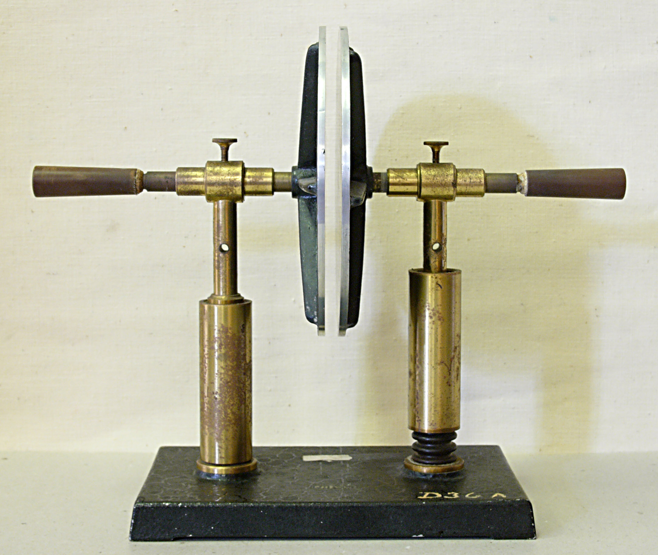
A schematic diagram is a diagram drawn to represent a real-life thing in a more abstract or symbolic way. We're going to be looking at electrical circuits in this course, for example, and while it can be useful to see a photo of the circuit, a simple schematic diagram is often less confusing.
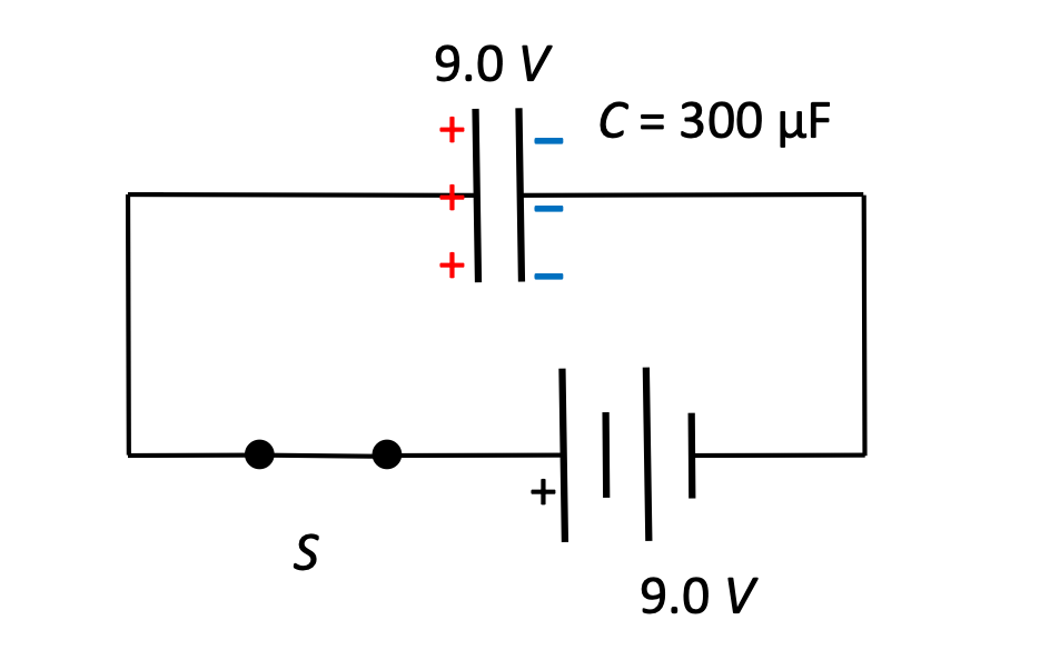
In this photo, for example, we see a battery connected to a switch, which is connected to a capacitor, which is also connected to the other end of the battery. Such a photo can be useful when learning how to actually connect the components into a circuit.
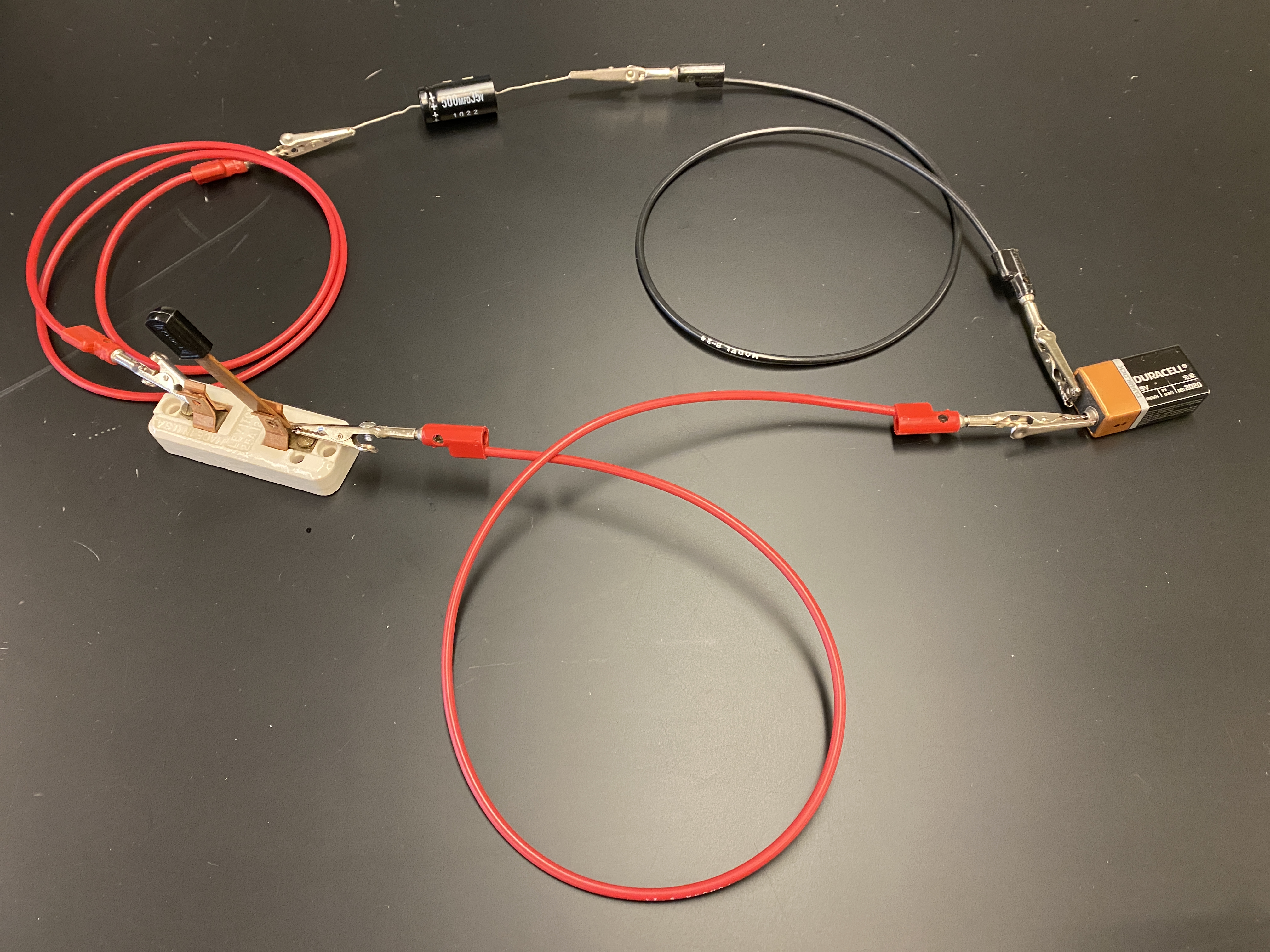
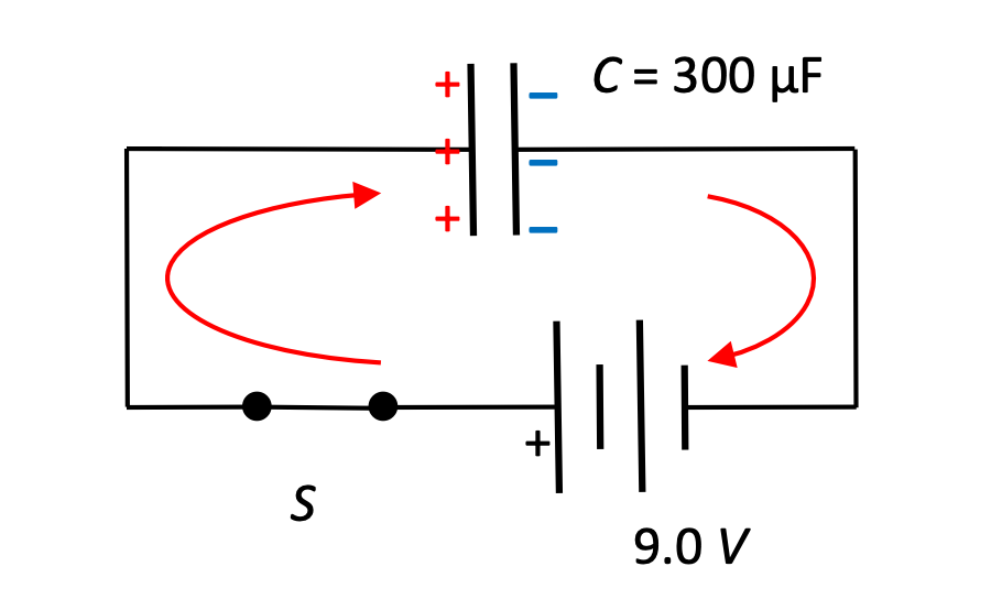
.If we're trying to understand the principles of a such a circuit, however, a better way of representing the components is this schematic drawing:

Here we can see the components clearly labeled and connected to each other. Note that the components often resemble aspects of their real life counterparts: the switch has a blade that drops down to complete the circuit, the symbol for a battery has long and short lines to represent the metal discs of Volta's battery, and the symbol for a capacitor represents the parallel plates that we've been studying.
So, how do we get charges onto the plates of the capacitor?
Let's follow conventional current, the movement of the positive "electron-holes," even though it's actually the electrons that are moving.
Once the switch S is closed, positive charges throughout the wire begin moving away from the positive end of the battery, and begin accumulating on the left plate of the capacitor. This has the effect of driving off positive charge from the right plate of the capacitor, leaving negative charge behind. Positive charges continue to flow in a clockwise direction through the circuit, driven by the potential in the battery, which is maintained by the chemical reaction going on within it.
As charges accumulate on the capacitor plates an electric field is created there, and a potential difference builds up between the positive and negative plates. This field has the effect of driving positive charge in the opposite direction, to the left. As long as the battery potential is greater than the capacitor potential, the battery will continue to deliver charges to the capacitor, at a decreasing rate however. Once the capacitor has reached the same potential difference as the battery, charges no longer flow. The capacitor has been charged.
Calculating charge
For the circuit shown above, a 9.0 Volt battery charges a 300 μF capacitor. Initially there is no net charge on the plates of the capacitor. How much charge is on the plates after the switch has been closed for a relatively long time?
The problem specifies that some amount of time has passed, because it does take some amount of time for the plates to charge up. The full charge is reached when the electric potential across the capacitor matches that of the battery: 9.0 V.

8.3.3. Capacitors connected in parallel and series
It's possible to connect multiple capacitors together in a circuit. One way to connect capacitors together is called "in parallel".
Capacitors in parallel

Capacitors may be connected "in parallel", so that charges flowing through the circuit will travel either to one capacitor or another.
The "equivalent" or "effective" capacitance of the two parallel capacitors can be calculated using the equation

It's important to understand how this relationship arises. One way to think of this is to consider that adding another capacitor, with a second set of plates, effectively increases the total plate size on which charge can accumulate. Based on this alone we might guess that, for capacitors connected in parallel.
Another way to demonstrate this relationship is to recall that charges continue to flow from the battery onto the plates of both capacitors until each capacitor has a potential difference across it that is equal to that of the battery. We also know that the total amount of charge driven by the battery onto the plates is split up between those two plates. Therefore:

Another way that multiple capacitors can be connected into a circuit is "in series," such that charges effectively move through both capacitors, one after the other. There is only one pathway through the capacitors.
Capacitors in series

Capacitors may be connected "in series", so that charges flowing through the circuit will effectively travel through both capacitors.
The "equivalent" or "effective" capacitance of the two parallel capacitors can be calculated using the equation

This result is perhaps a little less intuitive, because it implies that the equivalent capacitance of the two devices is actually less than the capacitance of either one by itself. Why would this be?
When the battery drives "positive" charge onto the left plate of C1, an equal amount of positive charge is driven off from the right plate, to be pushed onto the left plate of C2. In this arrangement, the amount of charge driven by the battery, the charge on C1, and the charge on C2 are all the same, while the potential difference that builds up on the capacitors varies. The total ΔV due to the capacitors matches the ΔV from the battery, so we can analyze the situation this way:

8.4. Energy in a Capacitor
Why do we even find capacitors so interesting? They have the ability to store charge as electric potential energy, and they have the ability to release that energy by pushing those charges back into a circuit very, very quickly.
Let's look at an example of how that can be done.
Definition: Energy in a Capacitor

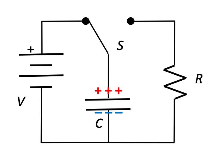
Examine the circuit shown here, in which a switch can be closed first on the left to charge the capacitor, and then to the right to allow the charge to flow through a circuit with some resistance R.
How much Work is need to store an amount of charge Q on the plates of the capacitor?
With qinst on the capacitor plates, there is a ΔVinst potential difference across them that changes as more and more charge accumulates.
One way of thinking about this is to try to figure out how much Work is required to separate those charges so they can be stored on those plates? A slightly different way of thinking about it, but one which yields the same result is: how much work does it take to transfer a charge dq from one side of the plates to the other?

This is an important result. The amount of electric potential energy stored in the charged capacitor can be easily calculated with this formula, or with variations on the formula derived using a simple substitution.

How much energy stored in this capacitor?
In this classroom demonstration, a potential of 6000 Volts is used to charge a 3.0 μF capacitor. How much energy is released when the plates of the capacitor are connected with a conductor?
Using the values given in the problem statement, we can select one of the capacitor energy equations for solving:

Also, this:
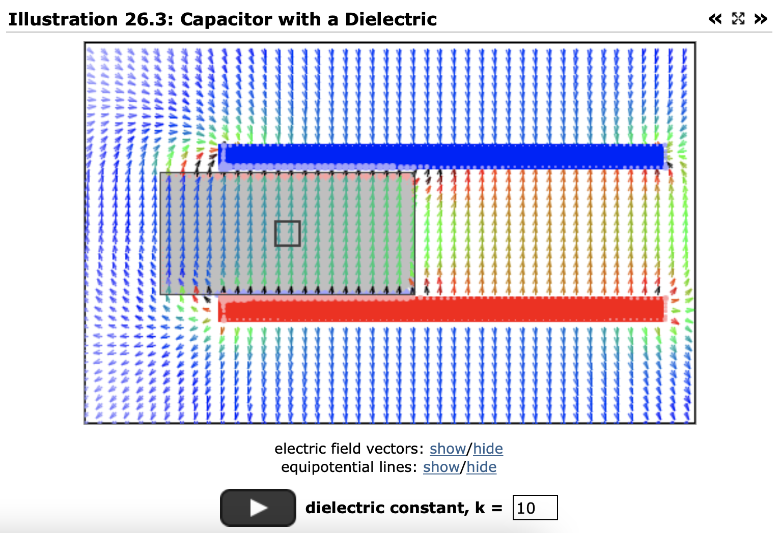
8.5. Dielectrics
An insulator inserted between the plates of an isolated parallel-plate capacitor causes a decrease in the potential difference between the two plates, a decrease of a factor Κ, the dielectric constant of the insulator.
Why? What effect does this have on capacitance of the system?
Before we look at dielectrics, let's review what we know about capacitors, electric fields, charge, and potential difference.
8.5.1. Electric fields and potentials in a capacitor
(Note: You can experiment with these diagrams interactively at https://www.compadre.org/Physlets/electromagnetism/illustration26_2.cfm.)
Capacitance, fields, and potential difference
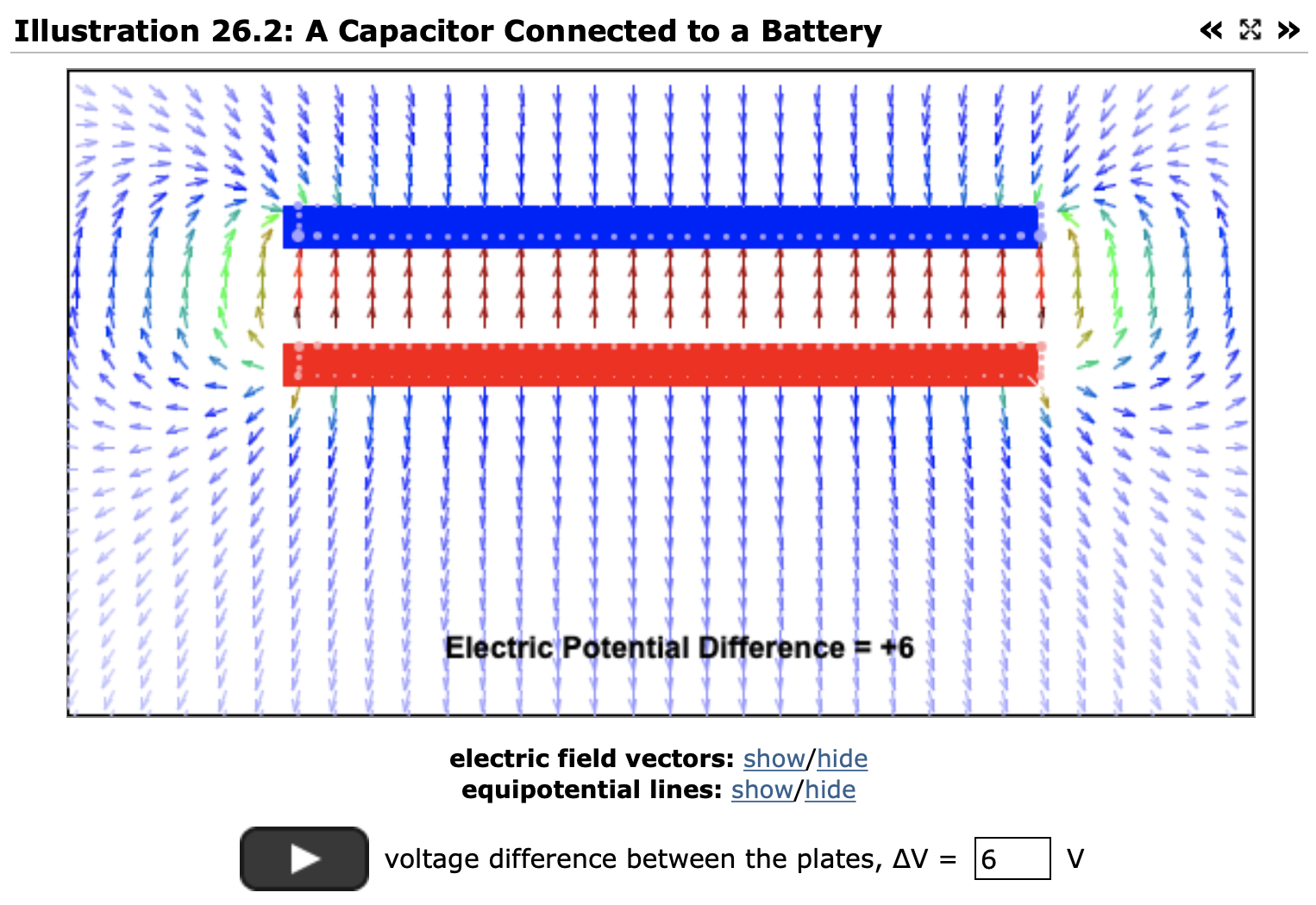
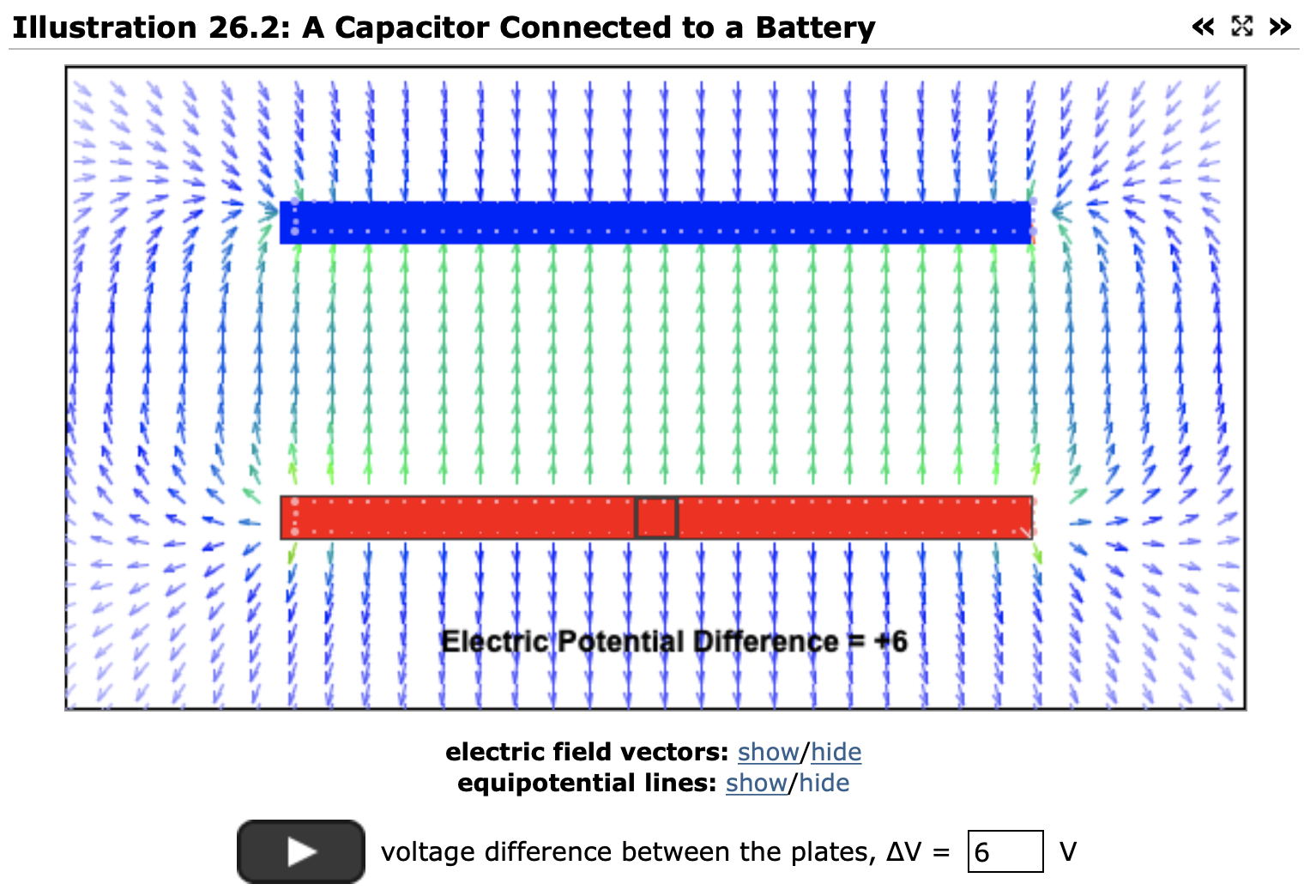
Examine the following parallel plate capacitor, connected to a 6.0 Volt battery so that there is a potential difference of Δ6.0 V across its plates. Note that there is an electric field created by that potential difference, a result of the charges (the white dots) accumulating on the positive (red) and negative (blue) plates. Notice the direction that the electric field points, the fact that the field is constant between the plates, although there is a characteristic fringing at the edges of the plates.
- How will the capacitance, charge on the plates, and electric field change if we increase the potential difference on these plates to 12 V?
- Going back to the original 6.0 Volt potential difference... what do the equipotentials look like around these plates?
- How will the capacitance, potential difference, charge on the plates, and electric field change if keep the battery connected, and move the plates so that they are twice as far apart?
- What do the equipotentials look like when the plates are twice as far apart?
- Going back to the original 6.0 V difference across the parallel plates... what happens if we remove the battery before we move the plates twice as far apart? How are charge, capacitance, electric field, and potential changed now?
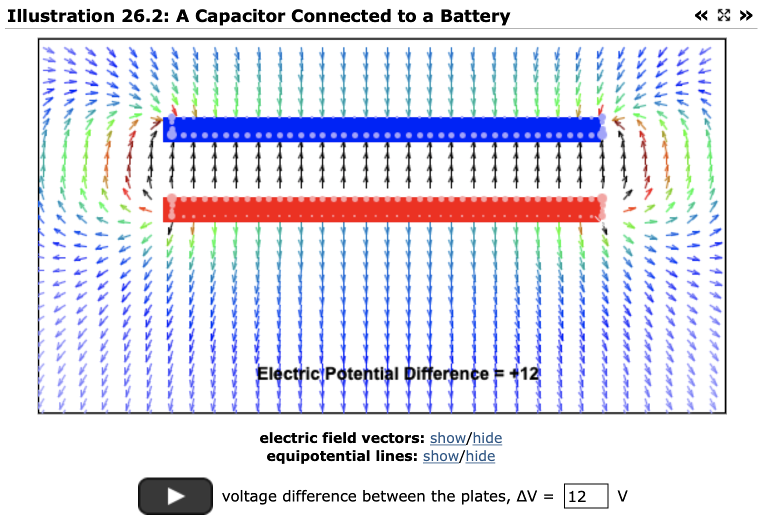
The capacitance of the system doesn't change—the plates have the same area and distance that they had before—but with a greater potential (push) on the plates, there is more charge on them. This also implies that there is a stronger electric field between the plates.
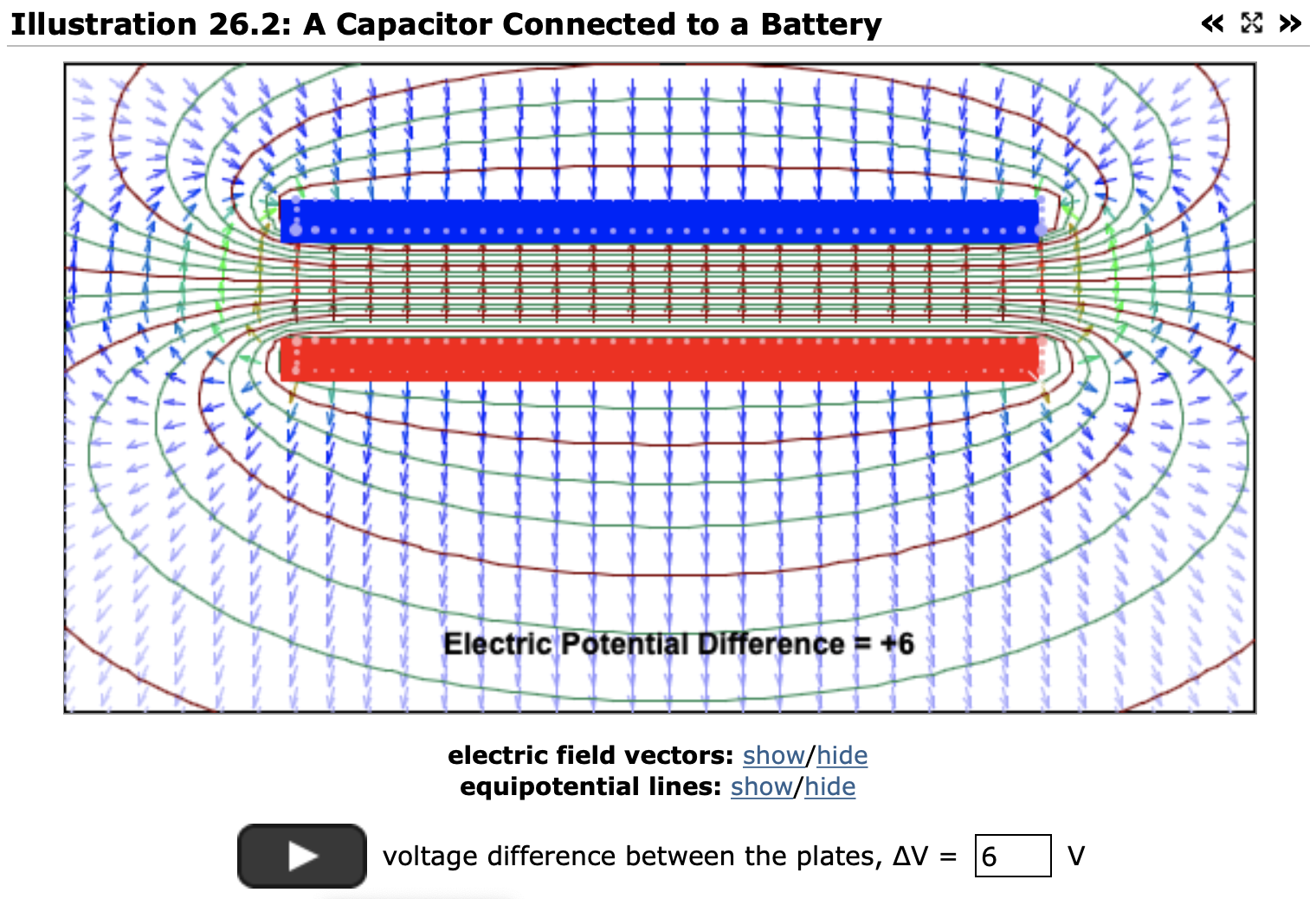
Equipotentials are oriented perpendicular to the field lines. Here, it looks like there are about 20 equipotentials draw in for that 6.0 Volt potential difference, or about 0.3 Volts per equipotential.
Now that the distance between the plates has increased, we expect that the capacitance of the parallel plates will have decreased according to

The battery connected to these plates maintains the same potential difference across those plates, so we still have ΔV = 6.0 V.
Based on Q = CΔV, we expect that there will be half as much charge on the plates, and based on ΔV = -Ed we expect that the electric field will have decreased by a factor of 2.
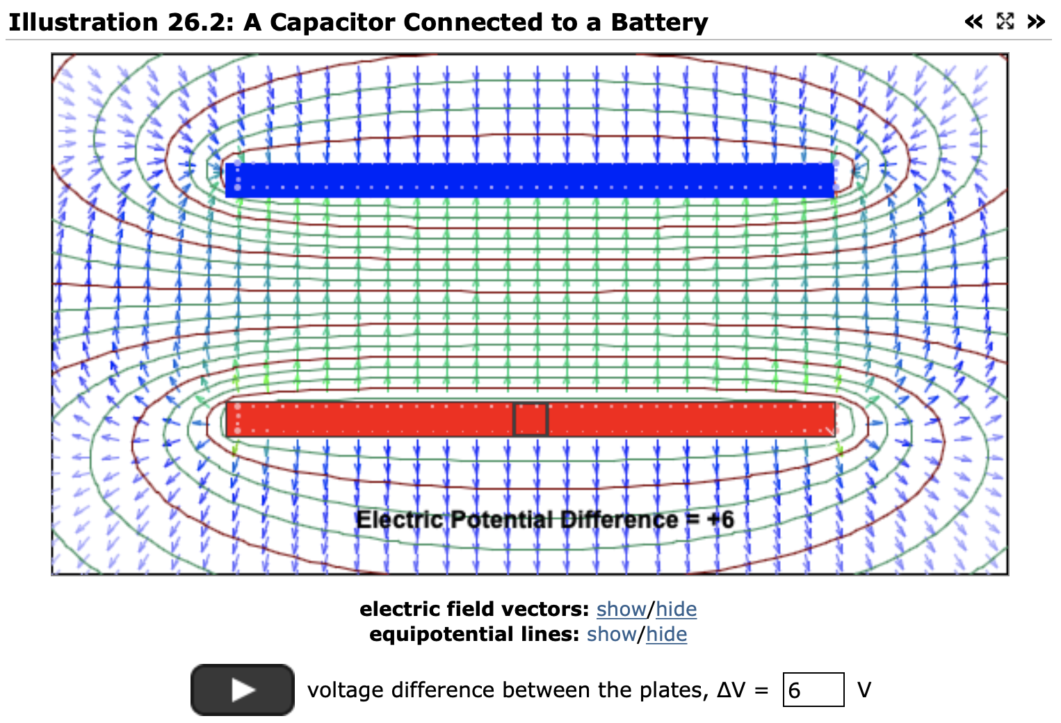
The electric potential of 6.0 V is maintained across the plates by the battery, so we still have those 20 equipotentials. They are just spread further apart, an indication that the electric field as weakened, as predicted by:

The charge will be maintained at the same level—there is nowhere for that charge to go. The capacitance of the system is less than it was before, revealing that the potential difference between the plates has... increased!
And according to ΔV = -Ed, the electric field remains the same!