Chapter 14: Inductance
14.0. Overview
At this point in the year, we know all four of Maxwell's equations, which summarize everything we know about electricity and magnetism.
Maxwell's Equations
- Gauss's Law
Electric charge distributions produce electric fields

- Gauss's Law for Magnetism
Net magnetic flux through any closed surface is 0 (no magnetic monopoles)

- Faraday's Law of Induction
Relates emf of a closed path to the rate of change of magnetic flux through surface

- Ampère's Law
Currents produce magnetic fields

We’ve already learned that a changing magnetic flux induces emf and currents, ie. electromagnetic induction.
In this chapter, we'll explore some consequences of induction, which include:
- Self-induction
- inductors
- mutual induction
- transformers
- RL circuits
- RLC circuits
Let's get started!
- Self-Inductance
- Inductance of a Coil, Solenoid
- Inductance circuits: RL, LC
14.1. Self-Inductance

Examine this simple circuit. When we throw the switch, we get a current from the battery that is the same everywhere throughout the circuit, according to Ohm's Law, V = IR. It turns out, however, that the current flow doesn't begin flowing immediately.
According to Faraday's Law:
- Current begins to flow (conventional current in a clockwise direction).
- As current increases in circuit, the current-carrying wire produces a magnetic field that, in the center of the conducting loop, is directed into the page. Therefore magnetic flux is increasing in the loop.
- Increasing flux induces an emf that opposes the change in net magnetic flux through the loop (Lenz's Law). The induced current fights the increase in flux with a magnetic field that is in the opposite direction, ie. the induced current attempts to flow counterclockwise.
- This opposing emf (or back emf) in the opposite direction of V produces a net emf such that the current increases gradually, and not instantaneously.
Defining Inductance
The self-inductance just described is the inductance that accompanies a circuit with a changing current. We can describe the emf due to the inductance and the changing magnetic flux as:

Note that the area of the loop through which the magnetic field is passing is constant, so flux just depends on magnetic field B, which in turn depends on the current I flowing in the circuit.

Because these quantities vary with each other according to some constant of proportionality, let's call that quantity the inductance L. We can then write:

Inductance L has the units [Volt - seconds]/[Ampere] = [Henry], and represents a "resistance to the change in current in a circuit."
It's helpful to be able to compare the relationships for inductance L and electrical resistance R:


Note that resistance R varies inversely with current (the greater the resistance, the less the current that is allowed), while inductance L varies inversely with changing current: the greater the inductance, the less quickly the current can change.
What are the factors that affect the inductance of a circuit? Is inductance a good thing or a bad thing?
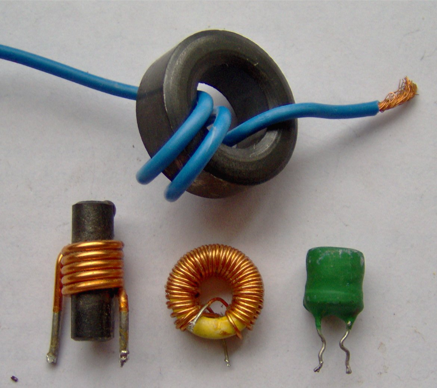
The coils of wire in the photo at the beginning of this presentation are all examples of inductors, so they must be good for something. Let's see.
14.2. Inductance of a Coil, Solenoid
We do like inductance—the ability for a changing magnetic flux to create an emf in a conducting loop—in some circumstances. The greater the effect of the changing flux, the greater the inductance. If we want a circuit to have a large inductance, however, the small self-inductance of a circuit such as the one shown above isn't enough. We need to use an inductor.
Inductance of a coil
Increasing the number of loops in a circuit or a coil increases the magnetic flux proportionally, and thus increases the inductance of a circuit.

Even better than a coil for creating a magnetic field, however, is a solenoid.
Inductance of a solenoid
Using the relationship developed above, let's calculate the inductance of a solenoid of cross-sectional area A, with N turns of wire in a length L:

It's more customary for us to express number of turns N per length L as n, so we'll make that substitution here. We can also take length L times the cross-sectional area A to get volume V:

Calculating inductance of a solenoid

Calculate the inductance of a solenoid that has 300 turns of wire in a 25.0 cm length, w/ a cross-sectional area of 400 cm2. Then calculate the self-induced emf in the solenoid if the current is decreasing at a rate of 50.0 A/s.
Solution
14.3. Inductance circuits: RL, LC
Now that we know a little more about how inductors can be described, let's see what effect they can have on various types of circuits.
14.3.1. The RL Circuit
Circuits with a coil/solenoid in them such as the one shown here have an inductance L due to the presence of the coil—the self-inductance due to the geometry of the circuit, in these cases, is considered negligible.
What happens in this circuit when the switch is closed at time t = 0?
Analyzing an RL Circuit

When the switch is thrown, current begins to flow in the circuit in a clockwise direction. As current increases with time, the inductor resists this increase with a self-induced "back emf," which reduces the rate at which the current would be increasing.
The current does continue to increase, although the current's rate of increase decreases... and thus, so does the back emf. After a long period of time has passed, the current reaches a steady state where I = V/R.
As we did with an RC circuit, we can perform Kirchhoff Loop Rule analysis of the potential changes around the circuit. (Note that there is a drop in potential from left to right as current flows across the inductor.)

This result

... probably looks familiar to you. It's of the same form as the charge on the plates of a capacitor as it's charging up in an RC circuit:

It's useful to be able to visualize what the graph of this current is as a function of time.
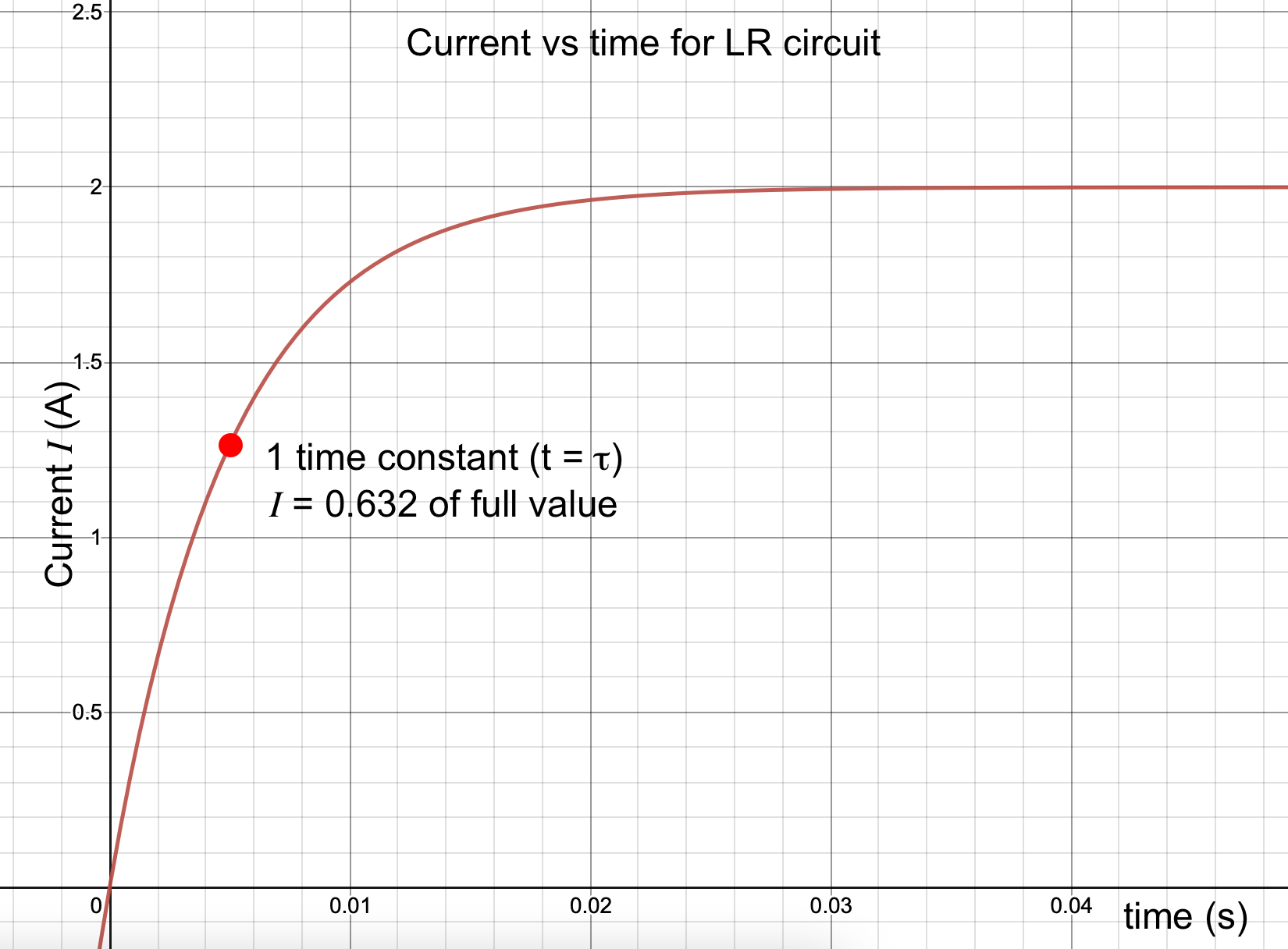
An RL circuit
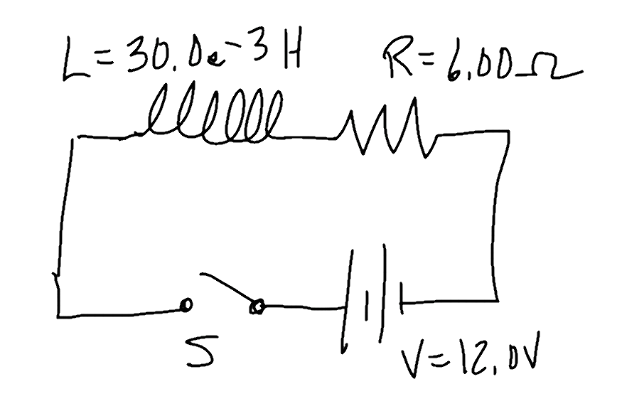
An RL circuit is constructed with a 12.0 Volt battery, a 6.00 Ω resistor, an inducting coil with L = 30.0 milliHenrys, and a switch.
- Draw a picture of the circuit
- The switch is closed at time t = 0s. Calculate:
- the time constant τ of the circuit
- the current just after the switch is closed
- the current at time t = 2.00 ms
- the current at one time constant
- the current a long time after the switch has been closed
Solution
14.3.2. Energy in an Inductor
Capacitors store energy in an electric field between their plates. That energy is built up over time as the field is created during the charging of the capacitor.
Inductors store energy as well, in the magnetic field within their coils. As current increases in an RL circuit, the magnetic field in the coils increases, storing more and more energy.
How much energy?
Energy in an Inductor
To identify how much energy is stored in an inductor, let's begin with a Kirchhoff's Loop analysis:

We're interested in energy, which is related to Power, so let's multiply all terms by I to get Power relationships:

Now, let's get rid of the dt and integrate both sides with respect to their different variables.

The energy stored in an inductor as a function of its inductance L and the instantaneous current I is U = 1/2 LI2.
14.3.3. The LC Circuit
We can learn more about inductors by considering how they interact with capacitors in an LC circuit.
Energy in an LC Circuit
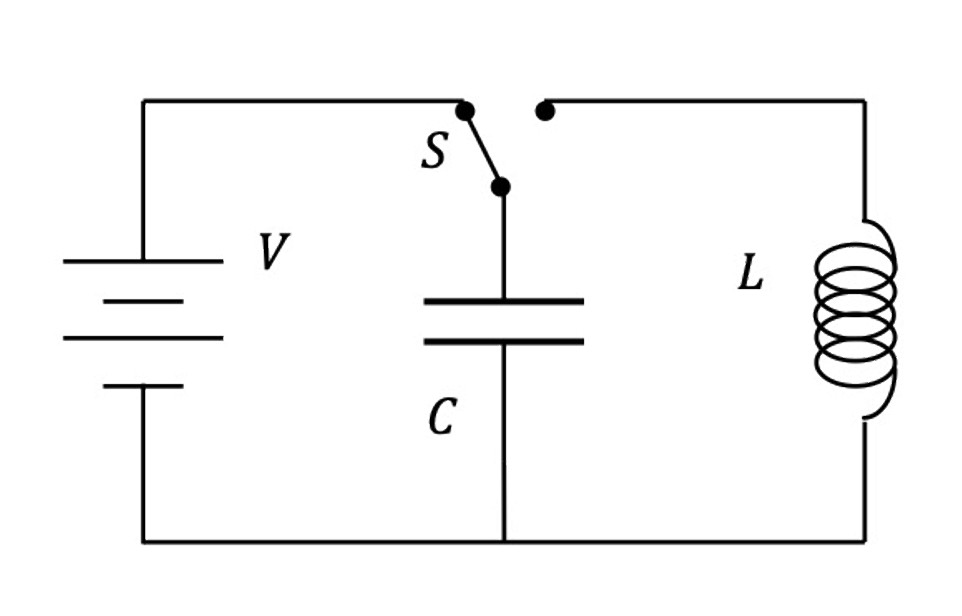
In the circuit shown here, a capacitor is charged by moving the switch to the left position. There is no current through the inductor because it is not part of a complete circuit. The capacitor, however, builds up charge on its plates, and the amount of energy stored in the capacitor is Uc = 1/2 Q2/C.
What happens when the switch is moved over to the right position, removing the battery from the circuit and connecting the inductor to the capacitor?
Qualitatively, the energy stored in the capacitor begins to dissipate as charge begins flowing off its plates and through the inductor. There is a "back emf" from the inductor that inhibits the current discharging from the capacitor somewhat, but still there is current building up through the inductor, building it's magnetic field and thereby storing energy in there according to U = 1/2 LI2.
The capacitor continues to push current through the circuit until it is completely discharged, at which time all of the energy in the circuit is stored in the inductor's magnetic field. The changing flux in the inductor is such that current continues to flow in the same direction (due to Lenz's Law, now being delivered via the induced emf in the inductor's coils. Energy in the inductor is dropping off now, and being stored in the capacitor again as charges build up on its plates, although in the opposite sense as they were before.
The current oscillates back and forth in the circuit as energy moves from the capacitor to the inductor and back to the capacitor.
At any point in time, if we disregard energy losses through the resistance of the wire, we can consider the total energy of the circuit as the sum of the energies in the components:

This brief animation demonstrates the principle well.