Chapter 12: Static Equilibrium
12.0. Overview
Objects in equilibrium have no net force acting on them, so they may be
- in motion (and not accelerating), or
- at rest (and not accelerating)
"Static" equilibrium obviously refers to the case in which the objects are at rest.
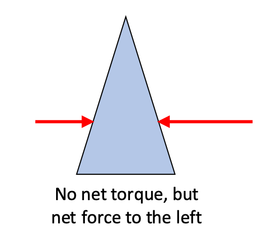
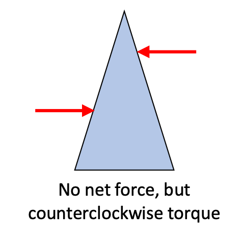
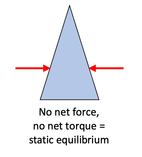
Objects that take up some area or volume can be in static equilibrium as well, but this requires an additional condition: the sum of the torques acting on them also has to be zero.
Let's see how we can use the Newton's second law of motion to analyze these situations.
12.1. Conditions of Static Equilibrium
There are two conditions that must be met for an object to be in static equilibrium.
Definition: Static Equilibrium
For an object to be in static equilibrium, it has to be not moving translationally (linearly), and not moving rotationally. It must not be moving relative to a given reference frame.
If this object is static—not moving—then we can also conclude that:
- the sum of the forces acting on the object must be zero.
ΣF = 0 - the sum of the torques acting on the object must be zero.
Στ = 0
Only if both of these requirements are met do we have a case that can be considered static equilibrium.
For us to be able to understand static equilibrium and be able to use it to solve problems, forces are obviously a key factor.
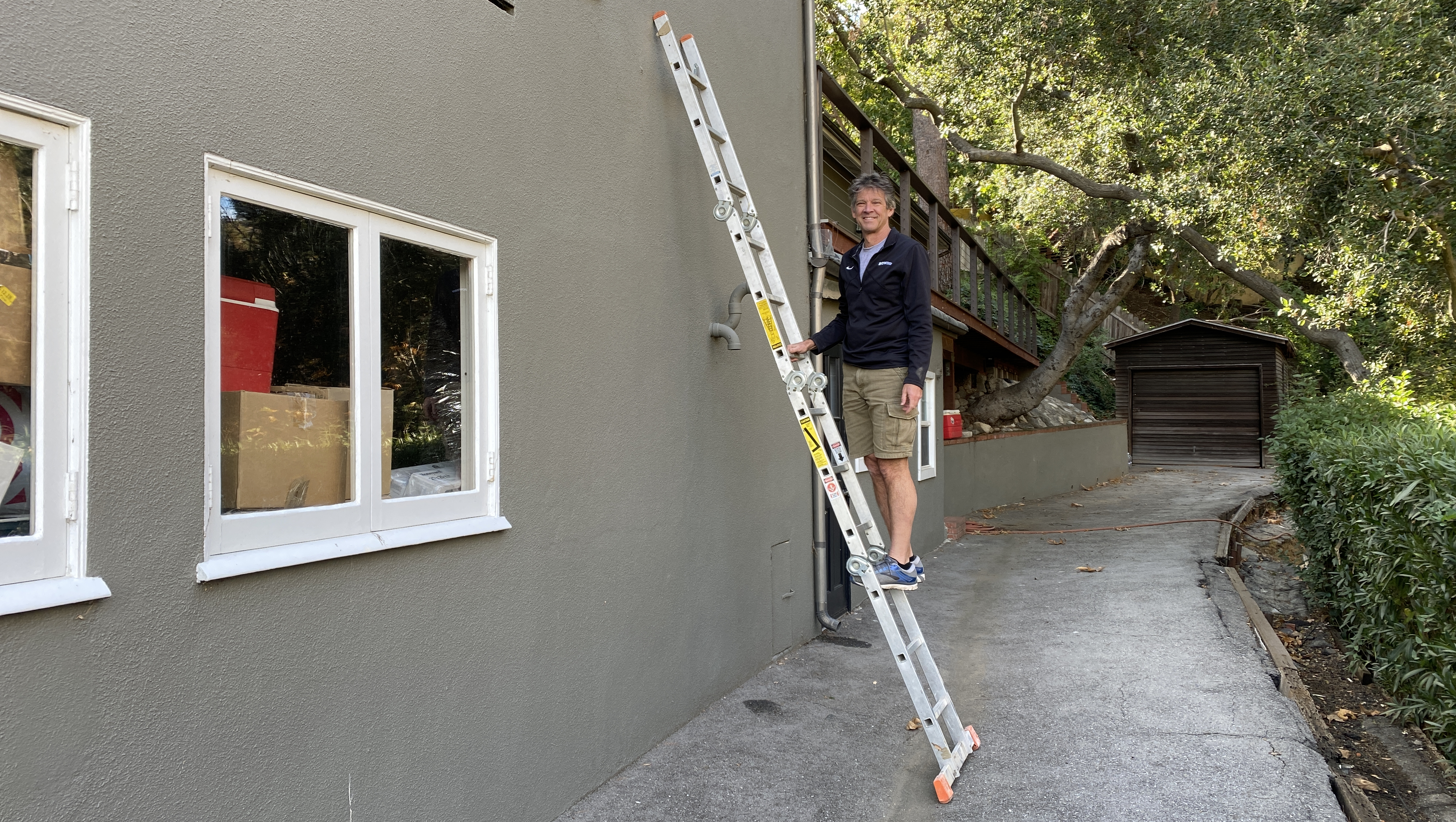
Free-body diagram for person on a ladder
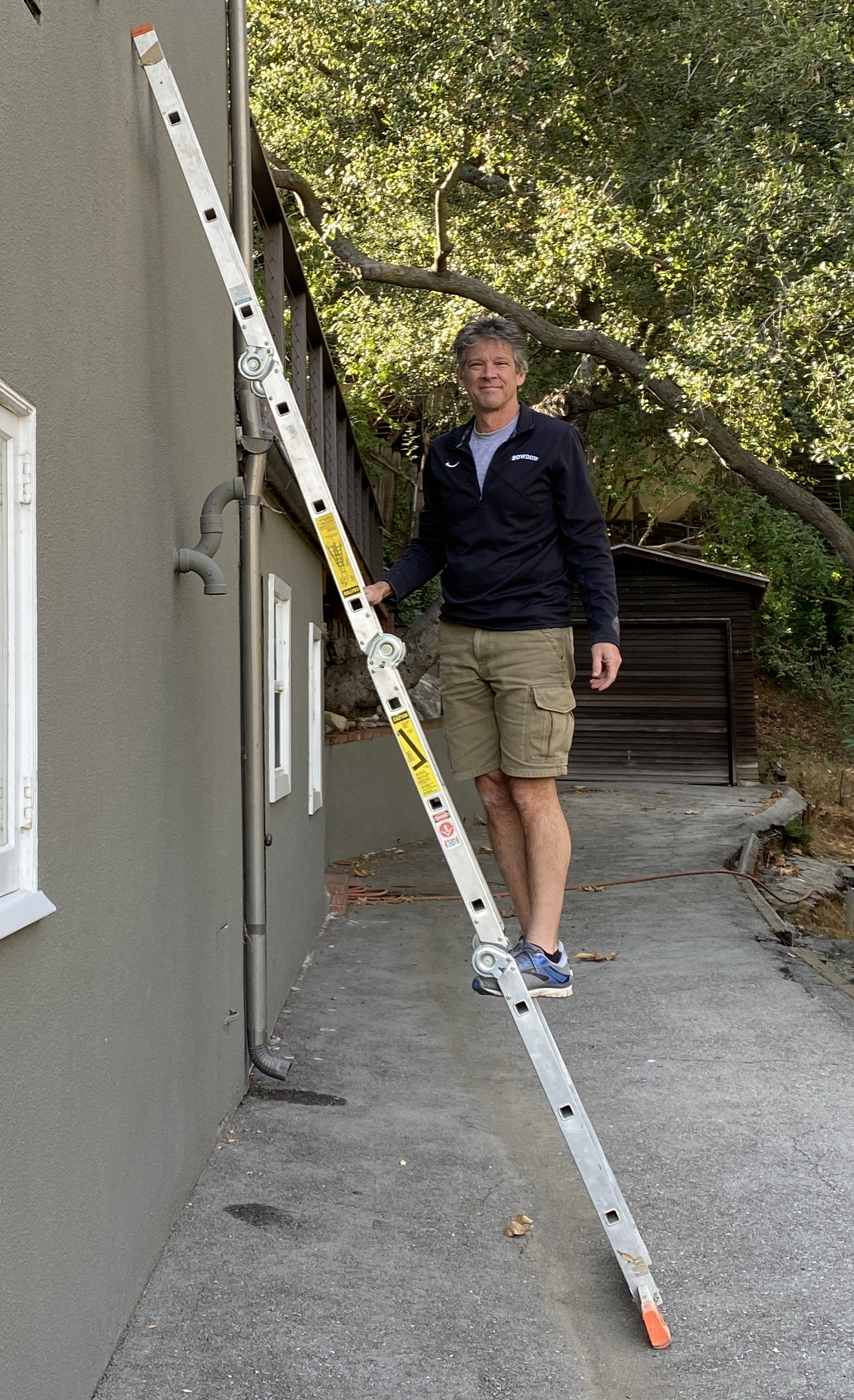
Using the situation shown here, draw a free-body diagram that identifies six forces acting on the ladder.
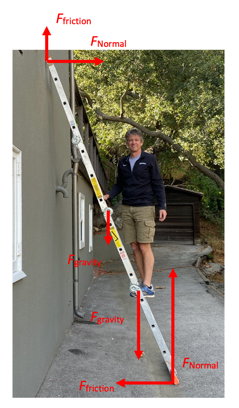
The forces acting on the ladder are shown in the diagram to the right. They include, from bottom to top:
- The normal force of the ground pushing up on the bottom of the ladder
- A static friction force to the left that prevents the bottom of the ladder from sliding off to the right
- The force of earth's gravity on the person standing on the ladder
- The force of earth's gravity acting on the ladder (at its center of mass)
- A normal force from the wall, supporting the ladder by pushing to the right
- A static friction force upwards that keeps the upper-end of the ladder from sliding down the wall
We'll be using these forces as well as the torques produced by these forces, calculated relative to some hypothetical axis of rotation about which the ladder might rotate. (It isn't rotating, however, because all of the torques are balanced.)
12.1.1. Where is the axis of rotation?
For an object that is in static equilibrium, where is the axis of rotation that we measure the torques relative to?
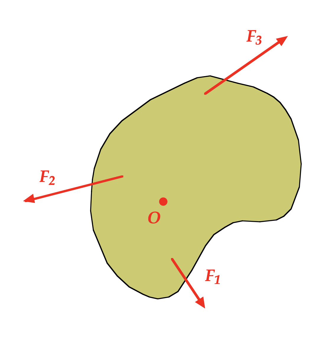
It turns out that if the forces all sum to zero for a a 2- or 3-dimensional object, and the torques sum to zero for a given point (axis of rotation) for that object, then the torques sum to zero for all points (axes of rotation) in that object.
We can demonstrate this mathematically.
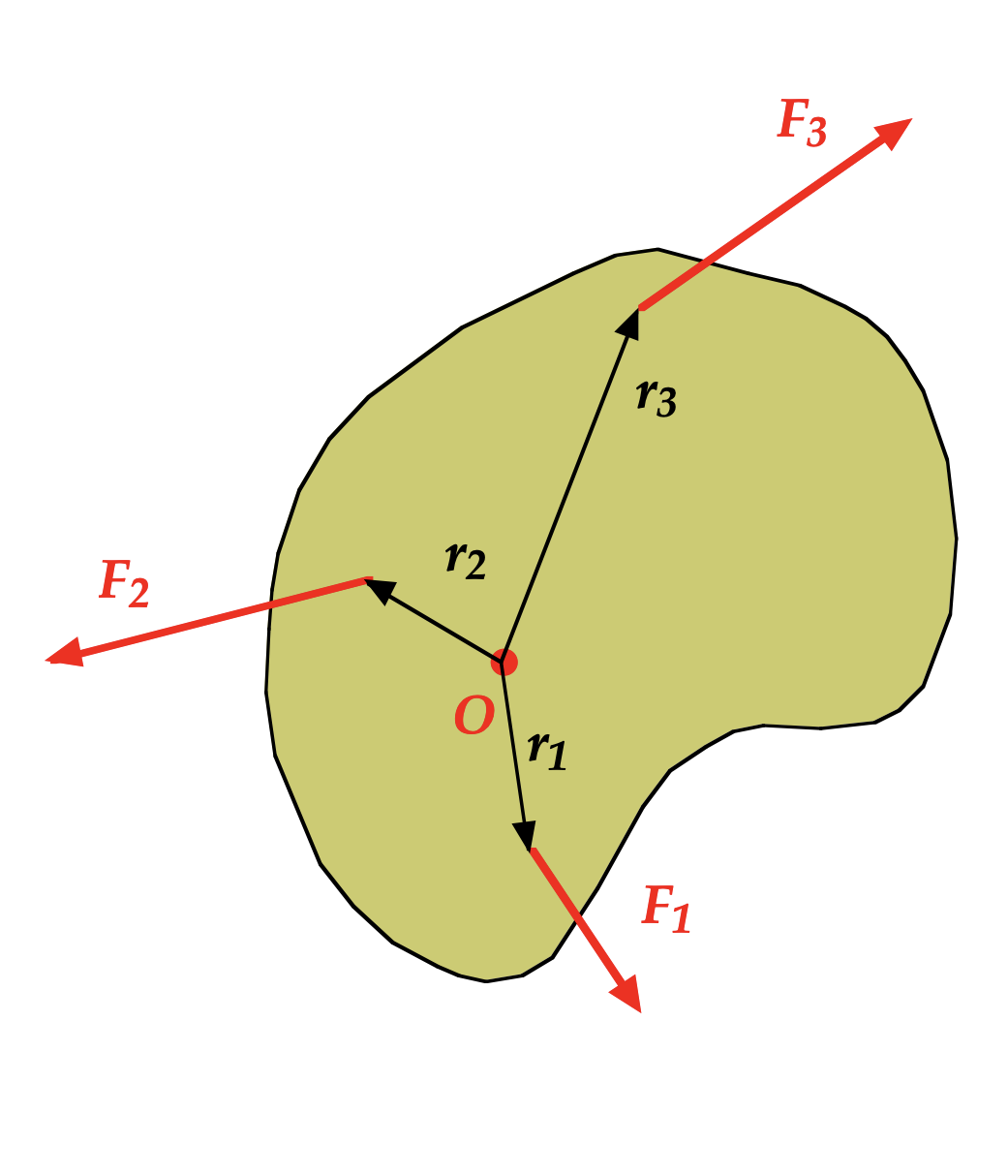
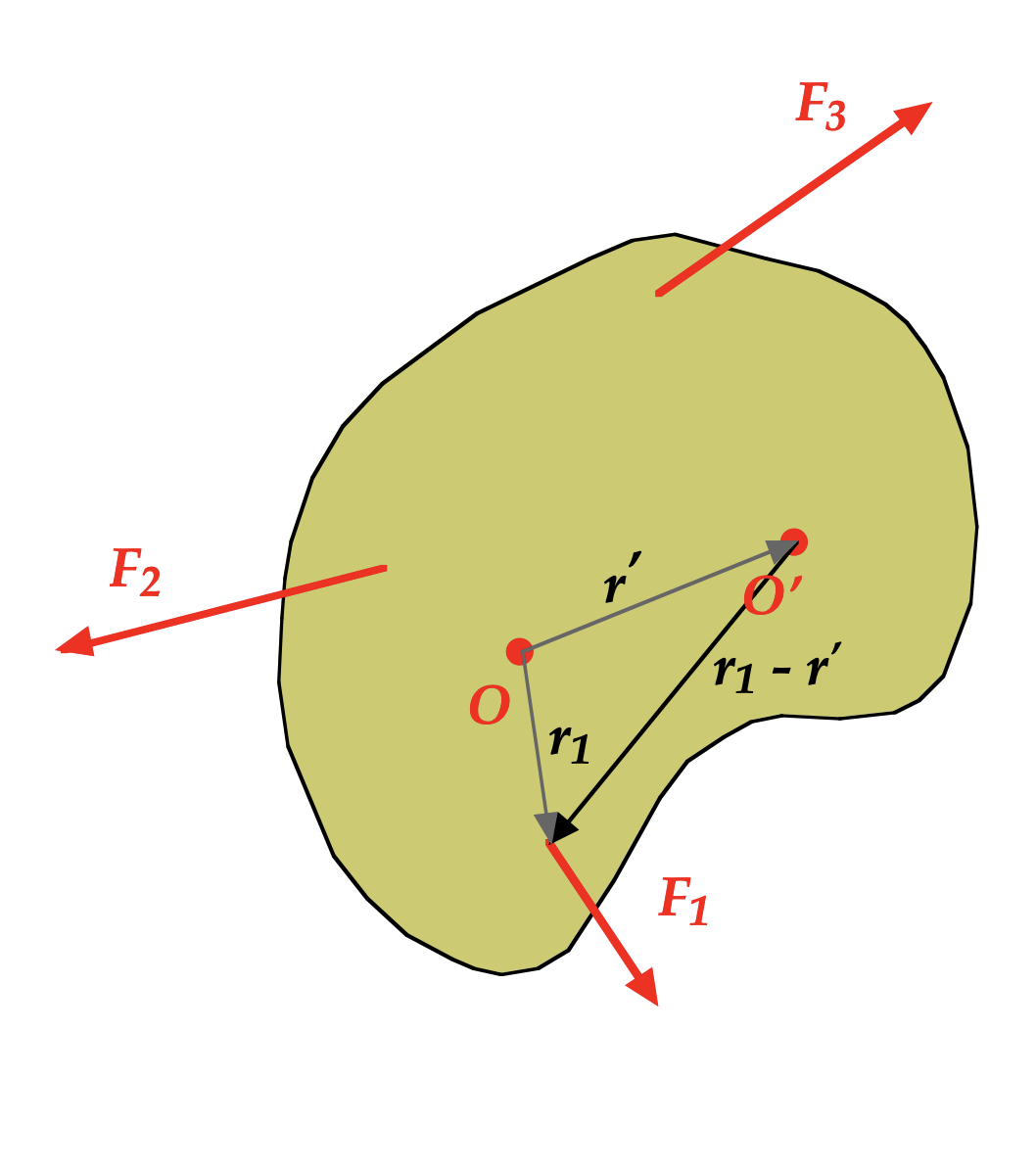
Let's take a look at the torque τ1 relative to the original point O from F1, which is r1×F1. If we locate a new axis of orientation O′, located at a displacement r′ from the original O, we can determine the torque relative to the new axis O′ as τ1′ = (r1 - r′) ×F1.
See the diagram above to confirm this relationship.
Extending that analysis to the other three forces and their corresponding torques, we have:
Coming soon!
12.2. Solving Static Equilibrium Problems
Solving static equilibrium problems involves a strategy similar to that we've used for other force-related problems:
- Draw a sketch!
- Draw a free-body diagram labeling all forces acting on the object. Guess the direction of forces, when necessary.
- Choose a convenient coordinate (x-y) orientation.
- Chose an axis for calculating Torque (preferably one that will make your calculations easier.)
- Write simultaneous equations and solve.
Let's see how we can solve some problems.
Lamppost
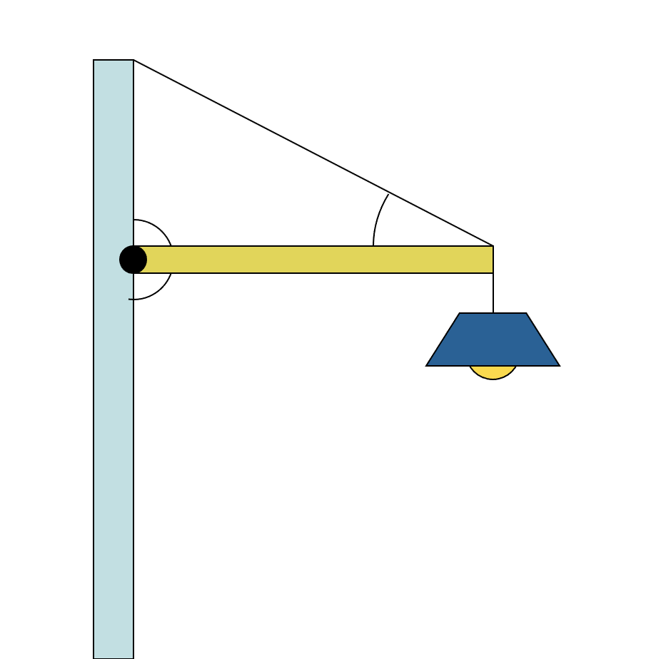
A 5.0-kg lamp hangs from a b) post as shown, supported by a hinged horizontal beam (L = 2.0 m, m = 3.0 kg) and a supporting cable oriented at 30 ° to the horizontal.
- Draw a free-body diagram of the horizontal beam and the forces acting on it.
- Calculate the tension in the supporting cable.
- Calculate the x- and y-components of the force acting on the hinged end of the beam.
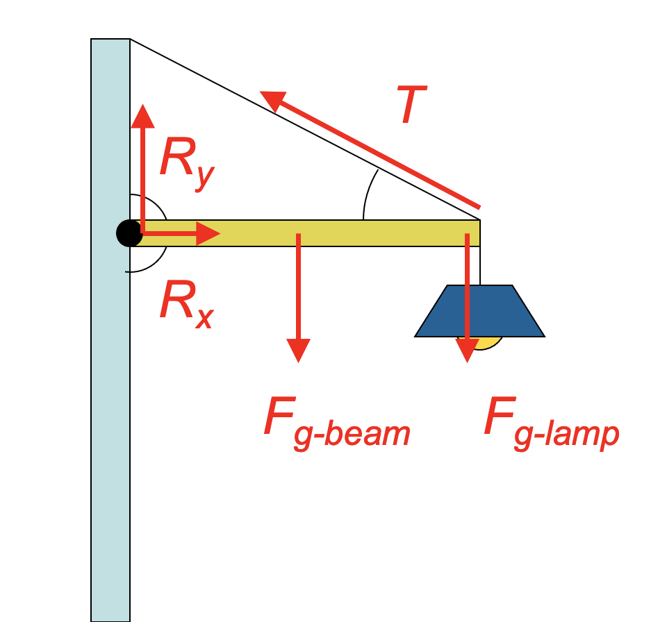 The free-body diagram for the horizontal beam is about what you would expect, although we're introducing a new strategy for helping to solve this type of problem. The hinge on the left end of the beam supplies a force that helps to keep the beam static, but we don't know much about it. In this diagram I've drawn the horizontal force acting on that end of the beam as Rx pointing off to the right, because I'm pretty sure I need a horizontal force to balance the x-component of the tension in the negative direction. I didn't know if the y-component of that hinge force R is up or down, so I'm guessing up, and we'll see how that works.
- To calculate the tension in the cable I'm going to have to use everything I know about static equilibrium problems, including ΣF = 0 and Στ = 0.
Let's solve for the torques first. Although I know I can use any point along the beam as my reference for the torque analysis, I'm going to choose to make the hinge my axis of orientation, for two reasons:- It's a hinge that rotates, and that makes a lot of intuitive sense to me as I do the analysis.
- I don't know the values of Rx and Ry, so if I consider the axis of rotation to be at that position, I won't have to try to calculate torques for that position—the r is 0 at that location.

- To get the components of force acting on the hinge in the beam, we can turn to our other sources of information, the sum of the forces in x and y directions.
 Note that our value for Ry is positive, indicating that our choice to make that vector pointing upward was correct. If we'd gotten a negative result from that calculation, that would have indicated that the direction for that vector should be downwards.