
Chapter 10: Rotational Motion
Topics covered in this chapter
After completing this unit you will:
- know how to use the angular measurements radians, degrees, revolutions, θ, ω, α
- be able to use rotational kinematics to solve problems
- be able to identify angular directions (using +/- or x-, y-, z-directions) for a right-handed coordinate system
- be able to define moment of inertia I, and calculate it both for systems of discrete masses and continuous mass distributions
- be able to use the parallel-axis theorem to solve problems
- be able to define torque τ, and given common examples of torque
- be able to calculate cross-products, including τ = r × F
- be able to calculate cross-products using i, j, k unit vectors
- be able to solve problems using Newton's Second Law in rotational form: τ = Iα
- be able to solve rotational Work and Power problems using rotational analyses
10.0. Overview
We've covered the three major components to our study of mechanics now: kinematics and Newton's Laws, Work & Energy, and Linear Momentum. Now we can start applying these concepts in a new set of circumstances: rotational motion.
Some people find that rotational motion means having to deal with a whole new set of equations. The best part about this unit, though, is that you don't need to learn any new equations! We've already seen all the equations that you're going to use!
They're just going to be expressed in a rotational frame of reference.
Let's get started!
- Angular Kinematics
- Moment of Inertia
- Torque
- Torque and angular acceleration
- Rotational Work and Power
10.1. Angular Kinematics
Angular (or "rotational") kinematics works just as our classic x-y kinematics does, but everything is measured in a circular reference frame.
10.1.1. Angular Displacement
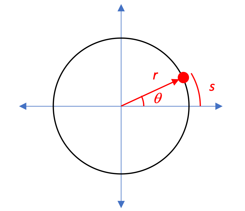
Consider the circle shown here, of radius r, which describes the circular path of a particle. The position of the particle can be described at any point in time by specifying its radius r from the center of the circle and its angular position θ relative to the +x axis.
Angular measurements
Although we've used degrees for most of our angle measurements up to this point, it's more convenient to uses radians as our preferred angular unit for these calculations.

Whereas an x-y position would be located relative to the origin at 0,0, our angular position θ is measured relative to the positive x-axis, as in your math class, with the positive direction being counter-clockwise.
10.1.2. Angular Kinematics
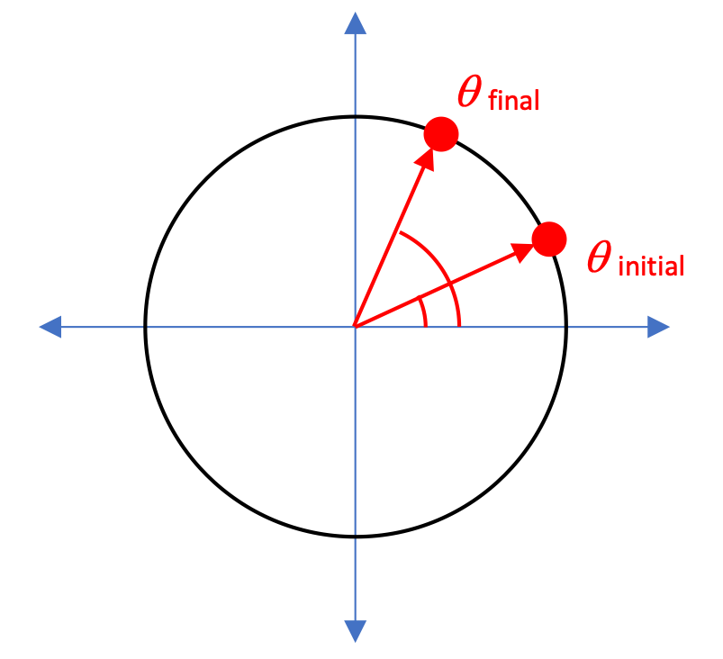
As we learned how to describe the motion of objects on a Cartesian-coordinate x-y grid, you recall that displacement Δx could be determined by xfinal - xinitial.
The same process occurs when we're looking at angular displacement Δθ: we can calculate the change in angular position as:

This change in angular position takes place over some period of time, of course, so in addition to just determining a change in angular position, we can calculate an angular velocity, designated with a lower-case "omega" ω.
This angular velocity can either be an average angular velocity or an instantaneous angular velocity, depending on which form of the calculation you want to do.

And as long as we're at it, let's go ahead and define angular acceleration as well. It follows the same strategy we used in defining linear acceleration:

Let's look at one more interesting aspect of our development. In the diagram here you can see that the arc length s represents a distance along the circular path of the moving object, a distance that we can identify as s = r θ.
What happens when we take the time derivative of that relationship?
The relationship between linear and angular measurements
Linear and angular measurements can all be determined by looking at their time-derivative relationships:

We can see in each of these that the linear and angular quantities are related to each other by the radius r of the circular motion.

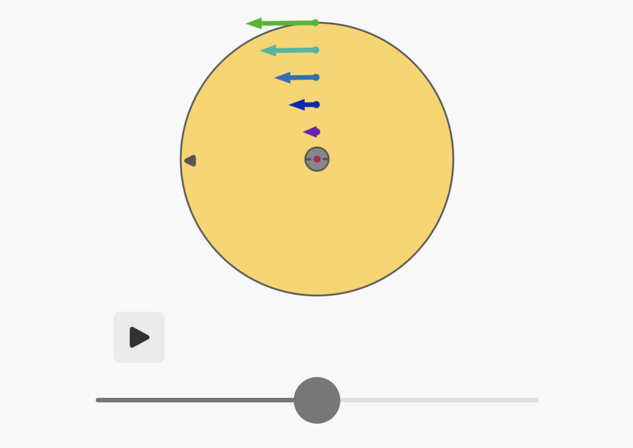
Interactive rotational animations
You may find it convenient to experiment with some of the interactive animations here.
With that in mind, it's we can now see what the angular kinematics equations are. These are exactly the same as the linear kinematics equations, with the exception of the radius r in each term, which then cancels out of the equation!
Kinematics Equations


We'll use these equations to solve a variety of problems. But first, let's look at positive and negative rotational directions.
10.1.3. Direction of Rotation
The question of positive and negative direction is just as important in rotational situations as it is in x-y systems. Here is how you can identify positive and negative rotations.
First, though, you need to know whether we're living in a right-handed or left-handed universal coordinate system.
Our right-handed coordinate system
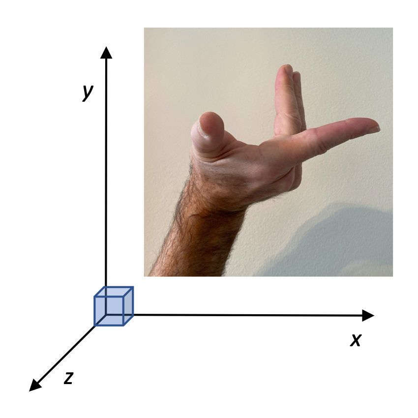
It turns out that we live in a right-handed coordinate system, just because that's how we started doing it, and we're not going to change it now. A "right-handed coordinate system" is one in which you can take your index ("pointer") finger on your right hand and point it in the positive-x direction, then half-bend the remaining fingers on your hand and re-orient your hand so those fingers are pointing in the positive-y direction. Your thumb now will be pointing along a third axis that is perpendicular to the plane formed by the other two. The direction that your thumb points is the positive-z direction.
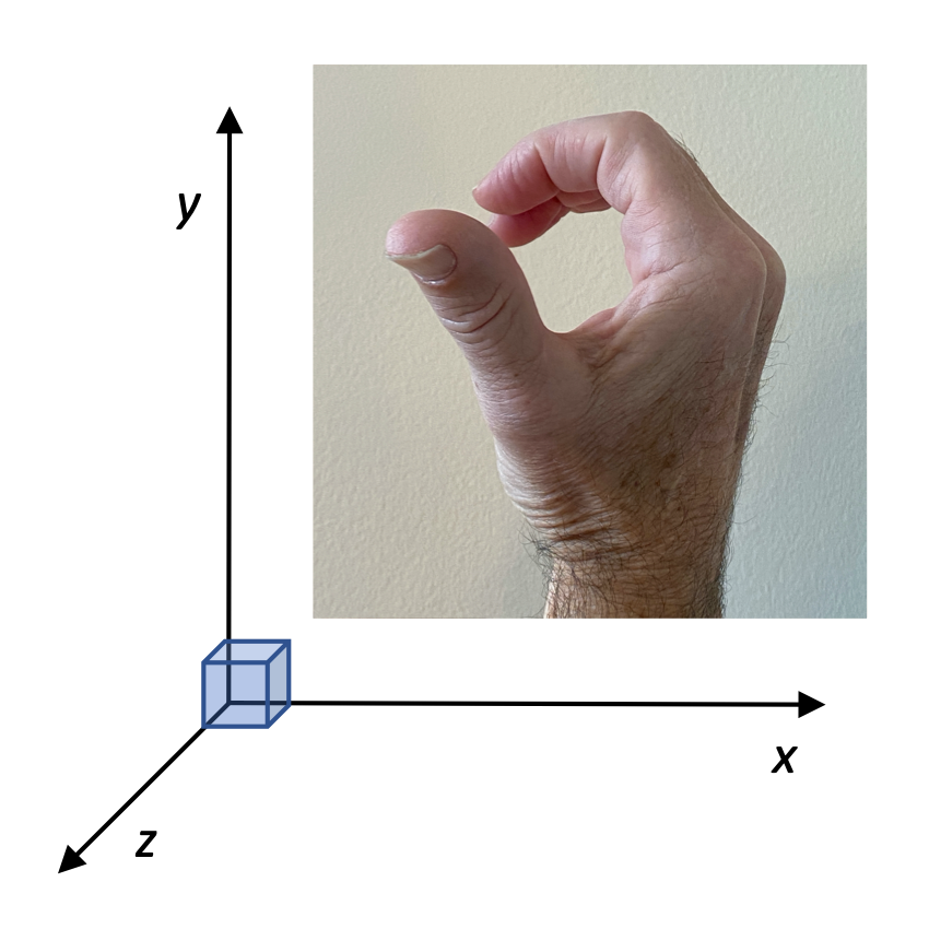
Now, if we have something rotating in the x-y plane, we can call that rotation "counterclockwise" or "clockwise", but we need to be able to assign a positive or negative value to those directions. Our convention is to again take your right hand, bend your fingers, and move your hand into a position where your fingers correctly match the direction of motion. Here, for a counterclockwise motion in the x-y plane, the right hand fingers are bent appropriately. The thumb, then, points in "the direction of circular motion, which is the positive-z axis. For simple problems, we'll just indicated that the direction of rotation is "positive," without specifying the z-axis.
10.1.4. Solving Problems
Let's see how we can use rotational kinematics to solve some problems.
Bug on a turntable
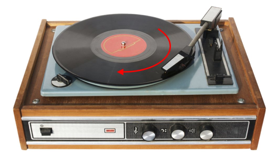
The turntable shown starts from rest, and begins rotating in the direction shown. 10 seconds later it reaches its final rotational velocity of 33.3 revolutions per minute.
- What is the turntable's final angular velocity (radians/second, mag and dir)?
- What is the turntable's average acceleration (mag and dir)?
- What distance in meters does a bug located 10cm from the axis of rotation, travel during the time the turntable is accelerating?


Wheel Turning
A wheel rotates with a constant angular acceleration of 3.50 rad/s2 . At time t = 0, its angular velocity is 2.00 rad/s.
- What angle does the wheel rotate through in 2.00 s?
- What is the angular speed at that moment?


10.2. Moment of Inertia
We're going to develop a new measurement that you probably aren't familiar with. To do that, let's first talk about rotational kinetic energy.
10.2.1. Rotational K
How can we determine the kinetic energy associated with the distributed mass of a rotating object?
All of the little mass components are rotating around an "axis of rotation," and each little mass has a different radius r and a different tangential velocity v. Let's add up the kinetic energies of all those little masses to get the total kinetic energy of the larger body:

Each of those instantaneous velocities is different, and depend on how far they are from the axis of rotation, a distance r. We can use the relationship vinst = rω, to bring in the angular velocity, which is the same everywhere throughout the rotating mass.

Here we've factored out the 1/2 and the ω2 which are constant for each little mass m. We're left with the expression in parentheses, which is a very useful expression for us. It's the "moment of inertia," I:

10.2.2. Moment of Inertia
The word "inertia" is something that we've used with mass to indicate its "resistance to changing its motion." The more mass something has, the more inertia it has, and the more difficult it is to accelerate it, whether you're trying to speed it up, slow it down, or change the direction of its velocity.
The moment of inertia I is analogous to the quantity m, and represents an object's resistance to having its rotation changed. Something that is really hard to get rotating like a Ferris wheel has a relatively large moment of inertia. Something that is really easy to get rotating like a "fidget spinner" or a pencil has a relatively low moment of inertia.
"Feeling" moment of inertia
To develop a feel for what moment of inertia is, try this exercise.
You'll need two long, thin objects with different lengths and different masses such as:
- a plastic straw and a metal pen
- a pencil and a ruler
- a drumstick and a nail
- a plastic spoon and a metal spoon
- a fork and a broom
- ... anything with different lengths and/or different masses
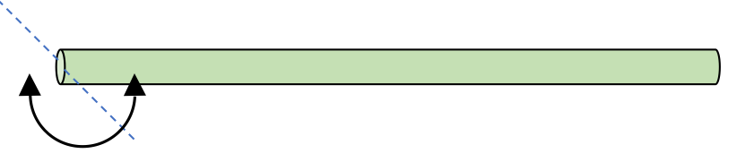
Take each of your two items, one at a time, hold them between our thumb and forefinger (or your hand if it's a larger object), and rotate the item back and forth as quickly as you can. You should be able to notice that one of the items is able to be rotated back and forth more easily than the other.
You should be able to feel it. In extreme cases you can even see which one is harder to rotate back and forth.
The object with the greater moment of inertia is the one with the greater "resistance to change in its rotation." It's the one that is harder to slow down and get rotating in the opposite direction.
Keep this idea in mind as we consider and calculate moments of inertia for various systems.
Which has the greater moment of inertia?
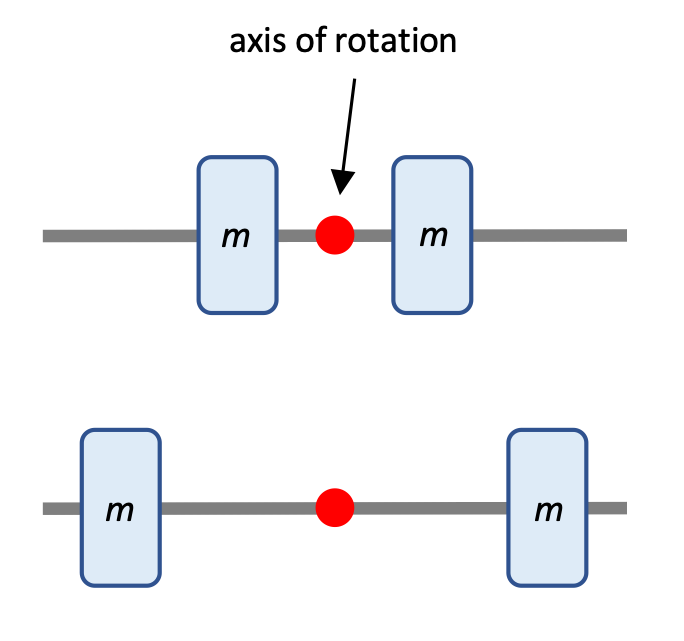
Here the masses are the same in each 2-mass system. Which one has the greater moment of inertia?
Both mass m and location of the mass r relative to the axis of rotation play a factor in determining total moment of inertia. In this case the system with the greater r is going to have the greater moment of inertia, all the more so because the r factor is squared.
The second system has the greater moment of inertia.
Which has the greater moment of inertia?
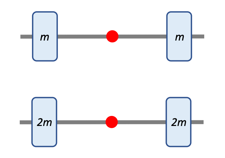
Here the distances from the axis of rotation are the same in each 2-mass system. Which one has the greater moment of inertia?
Both mass m and location of the mass r relative to the axis of rotation play a factor in determining total moment of inertia. A greater mass at the same distance from the axis results in a greater moment of inertia.
The second system has the greater moment of inertia.
Calculate the moment of inertia
2 children (each m = 20 kg) and 2 adults (each m = 70 kg) sit in seats on the teacup ride at Disneyland. The center-of-mass for the adults is located 70 cm from the axis of rotation, while the cm for the children is 80 cm from the axis of rotation. The mass of the cup itself is negligible in this problem.
- Calculate the moment of inertia of the people in the cup.
- The cup spins at 1.3 revolutions per second. Calculate the rotational kinetic energy of the people in the cup.
- I = 94.2 kg-m
- K = 3140 J
10.2.3. Moment of Inertia for Continuous Distributions of Mass
In the previous unit we looked at how we could determining the center-of-mass for a system built of discrete masses. We then expanded our analysis so that we could use an integral to analyze a continuous distribution of mass.

To be able to solve the integral form we used linear-, area-, or volume-based densities to substitute into the integral.

In the same way, in this unit we've looked so far at how we can calculate the moment of inertia for a distribution of discrete masses. If we consider those discrete masses as Δm chunks with a mass that approaches 0, we can develop an integral to analyze the moment of inertial for a continuous distribution of mass.

How can we integrate a function in r with respect to m? We'll use the exact same substitution strategy!
Let's try solving some problems with this tool.

Long thin rod about the center
Calculate the moment of inertia for a uniform rod of mass M, with length L, rotating about its center of mass.

Long thin rod about one end
Calculate the moment of inertia for a uniform rod of mass M, with length L, rotating about an axis at one end of the rod.

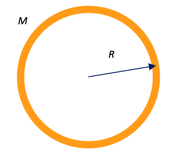
Uniform cylinder
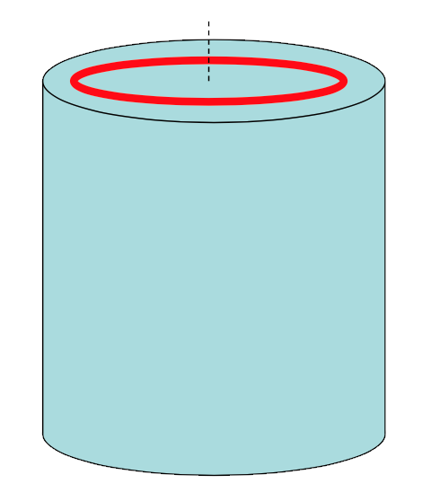
Calculate the moment of inertia around the central axis of a uniform, solid cylinder, with mass M, radius R, and length L.

10.2.4. Parallel Axis Theorem
Sometimes the axis of rotation passes through the center-of-mass of an object, as it does in the cylinder above. With a high degree of symmetry in a problem like that, we can easily solve for the moment of inertia.
In other situation, however, the axis of rotation may not pass through the center of mass. For these circumstance, the parallel axis theorem is a useful strategy.
Parallel Axis Theorem
If one knows the moment of inertia about the center-of-mass of an object, one can determine the moment of inertia about any other axis parallel to the original one using the relationship:

In this equation D is the distance from the center-of-mass of the object to the axis of rotation. As the name implies, the new axis of rotation has to be one that is parallel to the one described by Icm.
Let's use this to solve a simple problem.
Long thin rod
Use the parallel axis theorem to calculate the moment of inertia for a uniform rod, of mass M, with length L, rotating about an axis at one end of the rod.
Note that we've already solved this problem earlier, but that makes it a useful example for us to check our answer.
We know the moment of inertia I for a long thin rod about its middle, which is its length-wise center of mass:

If we're trying to find the moment of inertia I at the end of the rod, we have shifted the axis a distance D = 1/2 L. Thus, the I for the rod as it rotates about one end is:

This is the same result that we arrived at earlier.
10.3. Torque
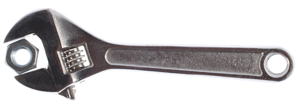
Torque refers to the turning effect produced by applying a force at some distance to an axis of rotation. One of the most obvious examples of applying a torque to something is that of using a wrench to tighten or loosen a nut.
More common examples of "torquing" something include:
- pushing open a door
- turning a faucet on or off
- turning the page of a book
- opening up the lid of your laptop computer
In all of these cases, a force applied at some distance from an axis of rotation produces a turning effect, or torque.
10.3.1. Definition of Torque
There are a number of ways to calculate torque, depending on the measurements you have.
Torque = rF sin θ
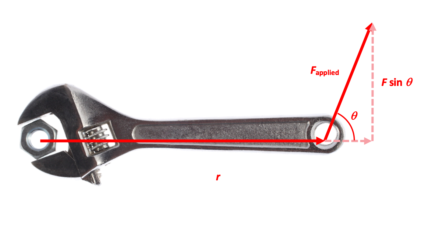
There are three factors in determining how much torque is being applied.
- the distance between the axis of rotation and where the Force is being applied—a greater radius distance means that more "leverage" can be applied
- the amount of Force being applied—a greater Force means that a greater torque can be exerted
- the angle between the radius and the direction of Force—a force perpendicular to the radius means that all of the force is being used to turn. As the force becomes less perpendicular to the radius, less of the force applies to turning. (A force parallel to the radius produces no turning effect at all.)
Because the turning effect requires a Force perpendicular to the radius, it is only the component of the force F that has any effect on torque. Therefore:

... where the Greek letter τ ("tau") is used to indicate torque, and θ is the angle between the directions of radius and Force.
Torquing a wrench
The wrench shown above is being used to turn a nut. A force of 85.0 Newtons is applied at the end of the handle, which is 38.0 centimeters away from the axis of rotation. If the force were applied perpendicularly to the handle there would be 32.3 Newton-meters of torque applied to the wrench. with a θ of 75 degrees, however, how much less torque is applied?

Just a little more than 1 N · m less.
There are a couple of other ways that we can calculate torque.
Torque = Fd, Torque = r × F
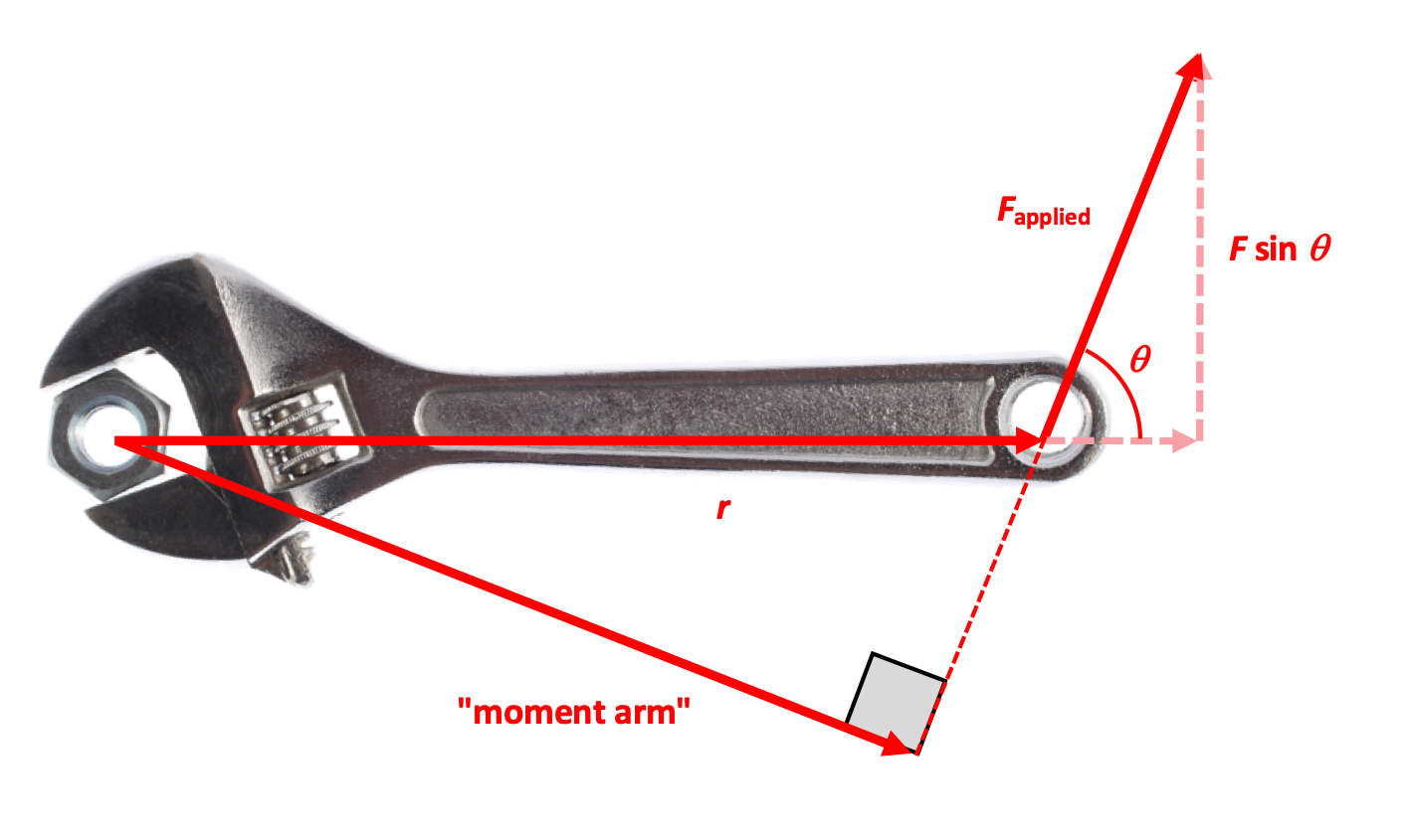
Another way of calculating torque is by using the moment arm, which is the shortest distance between the axis and the line of Force (see diagram). If the Force is applied perpendicular to the radius, the moment arm is the radius, but if the force is applied at some angle, they're different.
A simple geometric analysis should convince you that rF sin θ and dF are the same value.

The third way of calculating torque is by using a cross-product, which is our first opportunity to use such a calculation in this course.
Let's take a look at what a cross-product is and how one can calculate it.
10.3.2. Cross-Products
Before we look at at cross-products, let's review the dot-product.
10.3.2.1. Review of Dot-Products
One of the ways that we have of multiplying two vectors together is the dot-product: the two vectors are multiplied together by using their magnitudes as well as the cosine of the angle between them: the more parallel two vectors A and B are, the more their dot-product A · B approaches the product of the magnitudes, AB.
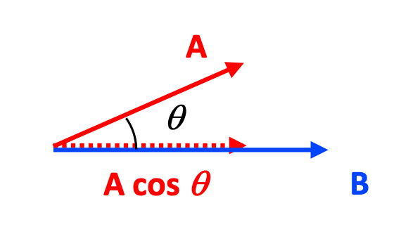
We used the dot-product to calculate Work done by a force acting over a displacement, and you recall that the dot-product produces a scalar result: there is no direction in the result (although a solution may be positive or negative).
10.3.2.2. Another way of multiplying vectors
A second way of multiplying vectors is the cross-product: the two vectors are multiplied together by using their magnitudes as well as the sine of the angle between them: the more perpendicular two vectors A and B are, the more their cross-product A × B approaches the product of the magnitudes AB.
One way of visualizing the dot-product is to consider a parallelogram with sides of length A and B: the magnitude of the cross-product is the area of the parallelogram. The closer the angle between those two sides is to 90 degrees, the greater greater the area (and the cross-product magnitude); the smaller the angle, the smaller the area (and the magnitude of the cross-product).
Another important difference between the dot-product and the cross-product is that the cross-product produces a vector result. This certainly makes sense in the context of torque: the direction of torque—clockwise or counterclockwise—depends on the relationship between the directions of the radius and the Force.
As we'll soon see, the factors in a cross-product are not commutative. Order matters. A × B ≠ A × B.
Let's see how to determine the direction of a cross-product.
Identifying the direction of a Torque
Referring again to our wrench, the radius vector r points from the axis of rotation to the right along the positive-x axis. This is our first vector, r.
The second vector is F, which points (generally) in the positive-y direction.
To identify the direction of Torque use a Right Hand Rule with your index finger pointing along the direction of the first vector (radius), and your other fingers bent in the direction of the second vector (Force). The thumb of your right hand now points in the direction of torque, which in this case is the positive-z axis, associated with a counter-clockwise rotation... which is what we'd expect for a wrench experiencing a torque this way.
10.3.2.3. Cross-products with i, j vectors
In the previous example we saw that the torque τ occurs perpendicular to the plane formed by r × F. Looking at these factors as unit vectors, we can see that +i × +j = +k.
What would the direction of torque be if the force on the wrench were in the downward direction, ie. the -y direction? We can easily predict that the wrench will be torqued in the clockwise direction, which you may recall is a "negative direction." We can verify that by using the Right-Hand Rule (RHR) with the index finger pointing in the +x direction, the the other fingers bent down in the negative-y direction. The thumb has to point away from us, in the negative-z direction.
This implies that, for the unit vectors, +i × -j = -k.
There are some other relationships that you should know as well.

A negative value for any vector carries through to the product.
Calculating with cross-products
Find the cross product of 5i + 6j and -3i + -2j. Then find the angle between the two vectors.
We can calculate the cross-product using the rules given above:

To calculate the angle, we can use the cross-product relationships:

Note that the final answer is not 16.4 degrees. Draw a diagram of the situation to see why!
10.3.2.4. Cross-products with determinants
Matrices can be used to express vectors, of course, and are a valuable tool in mathematics, physics, computer science (machine learning and artificial intelligence in particular)...
Here is how you can use matrices and determinants to calculate a cross-product.
Calculating a cross-product with determinants
To calculate the cross-product of two vectors, first express their components in matrix form.

We can express this 3 × 2 matrix in determinant form as follows:

If we expand those determinants and solve, we arrive at the i, j, k components of the cross-product result:

Calculate with determinants
Find the cross product of 5i + 6j and -3i + -2j using determinants

10.4. Torque and angular acceleration
If we apply a torque to an object that rotates, we causes it to accelerate. Pedaling a bike, pushing on a merry-go-round, flipping a coin into the air... these all apply a force at some radius to an object—a torque—that causes it to rotate.
How are that torque and the rotation of the object related?
The relationship between τ and α
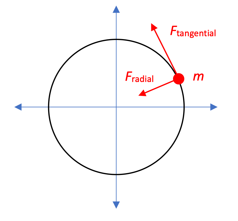
If we look at a mass m that is located at some radius from an axis of rotation, we can determine its moment of inertia:

If we apply a tangential force to the mass at that radius we are, by definition, applying a torque to the mass:

This in turn causes the mass to accelerate rotationally, an angular acceleration.

You may recognize the equation τ = I α as being equivalent in form to F = ma. We can use these two equations together to solve some very interesting problems!
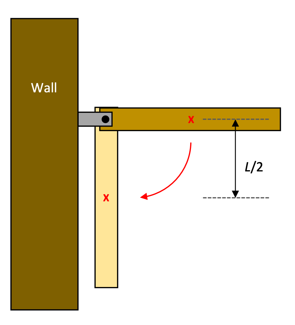
A hinged rod attached to a wall
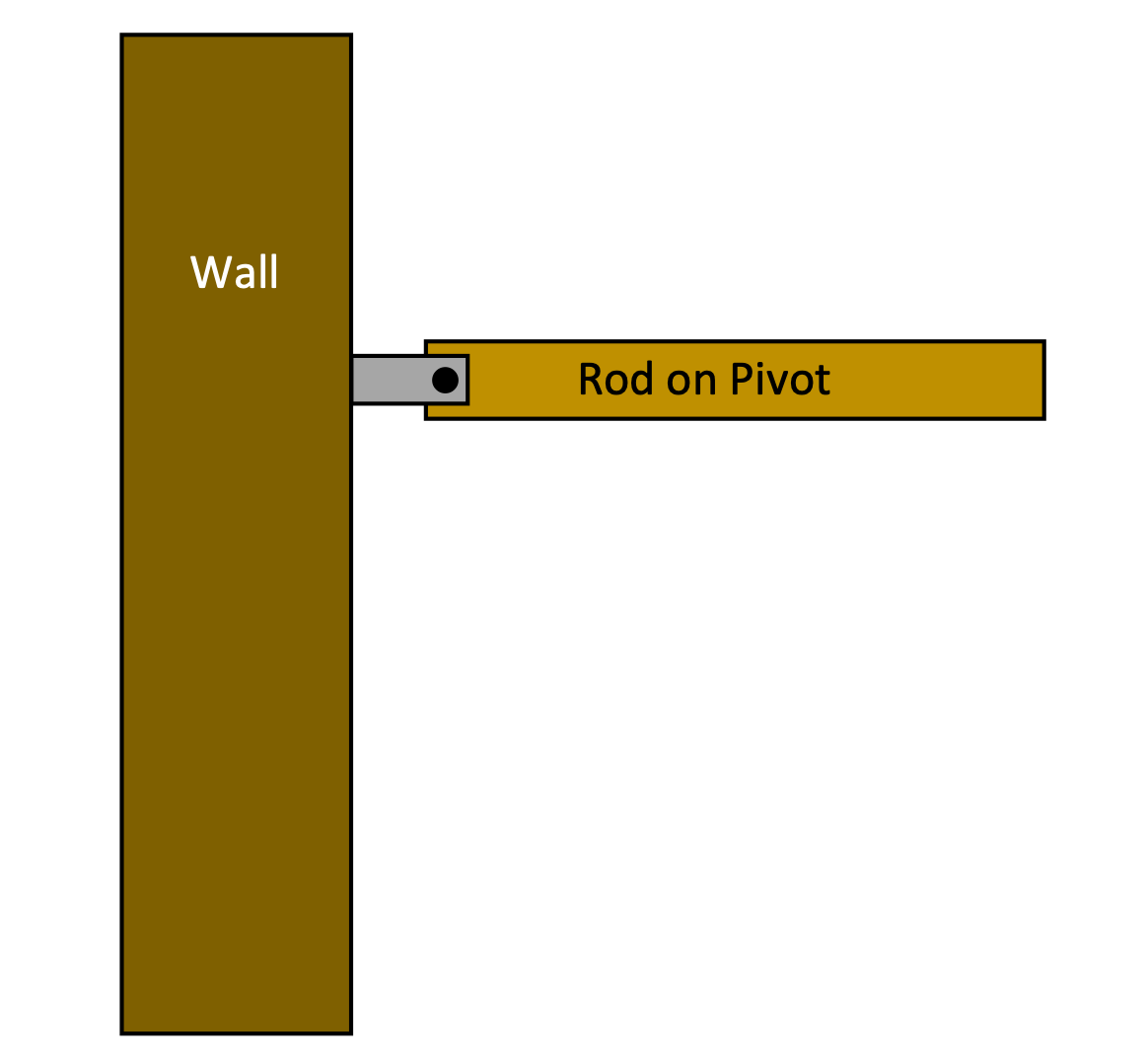
A uniform rod has a mass M and length L and can pivot as shown.
- If the rod is released from rest in the position shown what is the initial angular acceleration?
- What is the initial linear acceleration of the right end of the rod?
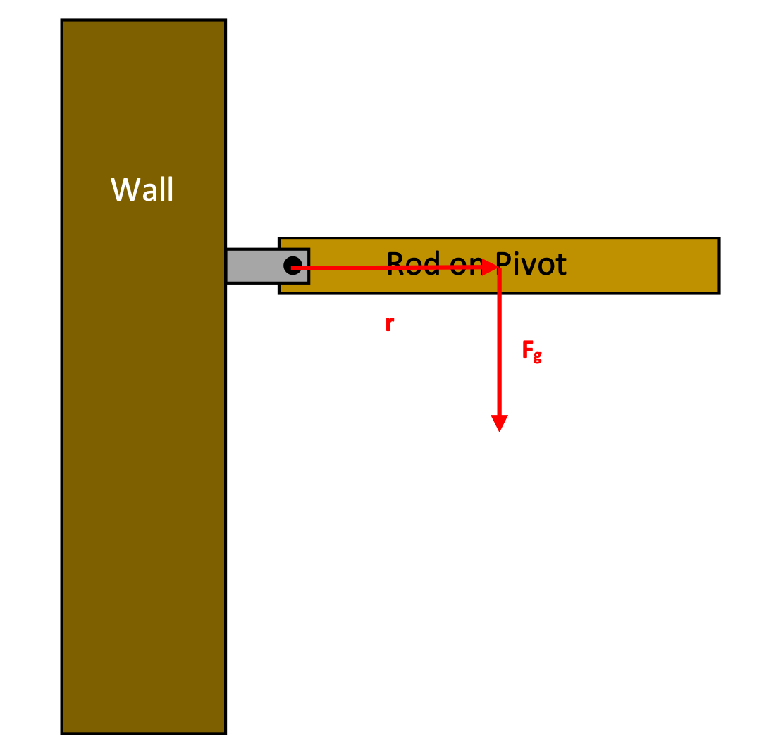
Because we're looking at accelerations caused by forces, we begin with a free-body diagram of the situation. (This diagram doesn't include all the forces acting on the rod, but we'll deal with that soon.)
The force of gravity acts at the center of mass, applying a torque that causes the rod to rotate downwards.
- To calculate the initial angular acceleration, we can use Newton's Second Law in rotational form: τ = Iα .

- And we can calculate the initial linear acceleration of the right end of the rod by using the relationship between a and α.

Note that the values we've calculated here are only for the rod at the given position. As it falls, the torque = rFg cos θ decreases, as a result of θ, the angle between r and F getting smaller. The rod is still accelerating downwards, but at a decreasing rate.
Mass hanging from a pulley
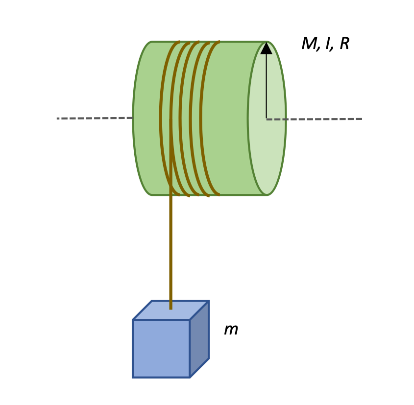
A cord is wrapped around the outer edge of a cylinder supported by an axle so that the cylinder acts as a pulley. A mass is attached to the cord and released so that it falls down, spinning the pulley as it goes.
Calculate the linear acceleration of the object of mass m, the angular acceleration of the wheel with mass M, radius r, and moment of inertia I, and the tension T in the cord.
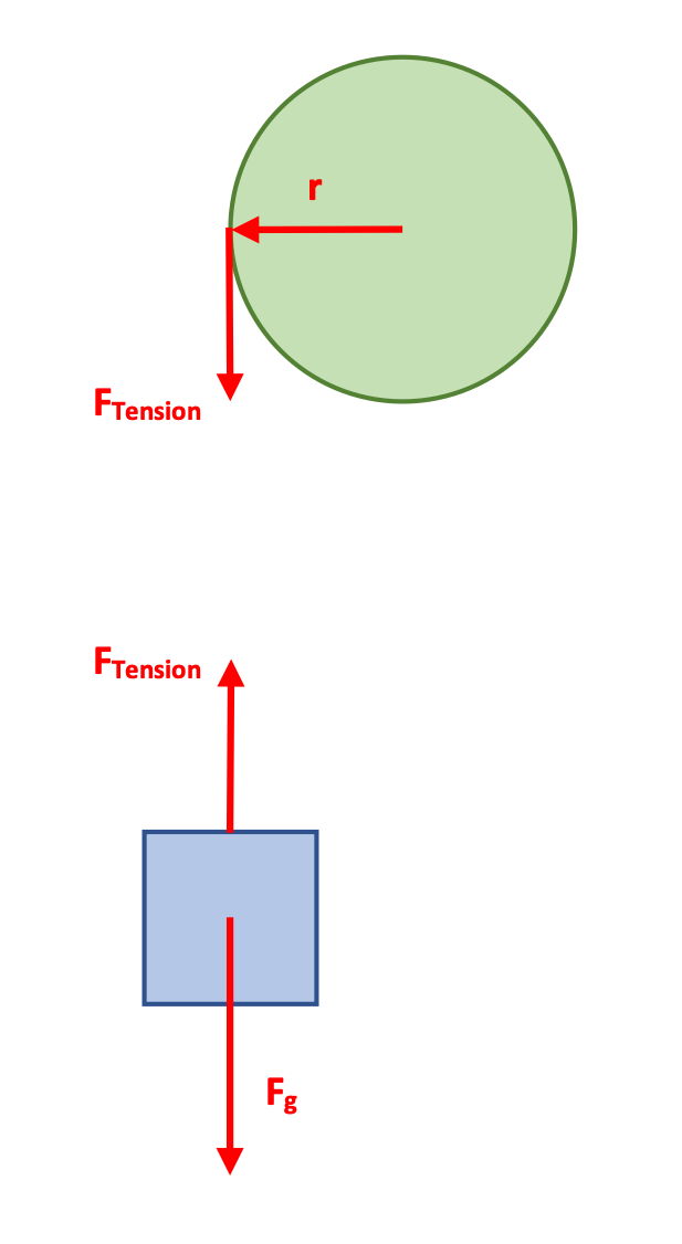
This is a classic Newton's Second Law problem that uses both linear (Fnet = ma) and rotational (τ = Iα) forms of that relationship.
10.5. Rotational Work and Power
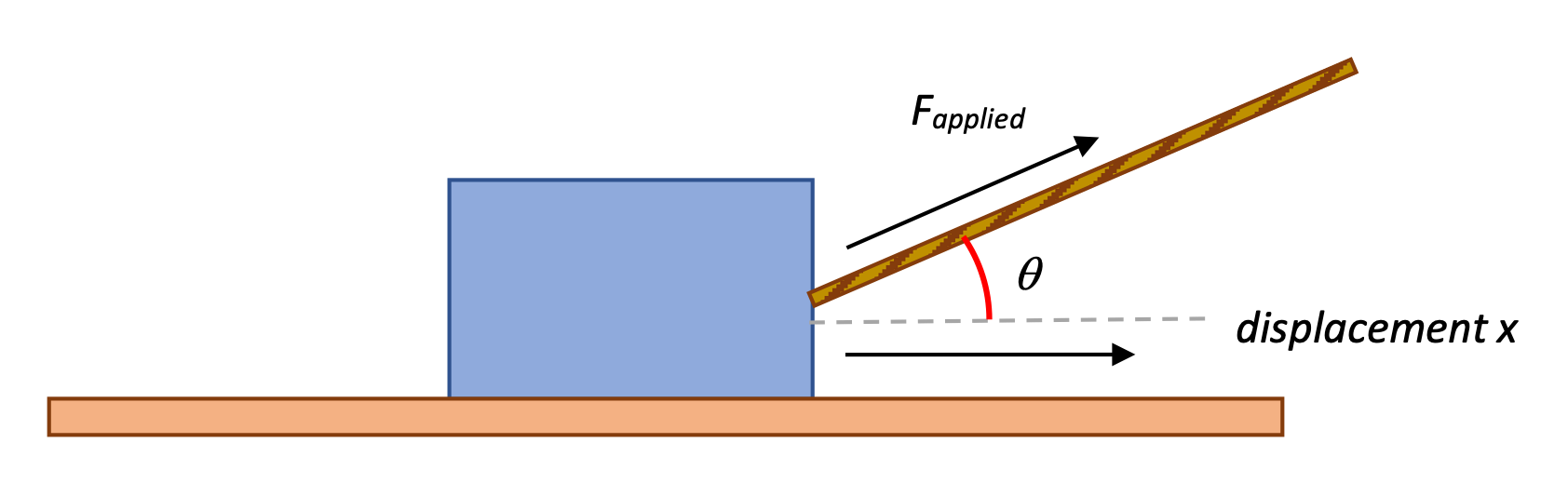
You may recall that we defined Work as a quantity related to a Force applied along some axis while the object moves along that axis.
Over a small distance dx the Work done by the x-component of force is

We determined the total Work done by integrating the Force over that displacement.

10.5.1. Work done by a Torque
How can we apply this analysis to a torque τ doing Work on an object, causing it to rotate by some angular displacement ɸ?
Torque doing Work
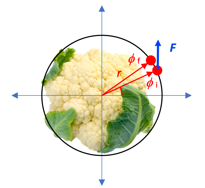
A force acting at some radius from an axis of rotation causes a Torque to be applied, which does Work on the rotating object.

Note that the rotational relationship is analogous to the original Work integral .
10.5.2. Torque's effect on Kinetic Energy
You may recall that a Force applied over a distance does Work on an object, and changes its kinetic energy.
Is there an analogous situation, with torque producing a change in kinetic energy?
Torque changes Kinetic Energy
Use τ = I α and the rotational Work integral to show that the Work done by a torque on a rotating object produces a corresponding change in the object's kinetic energy.

We can summarize this relationship by designating a value Krotational:

It's easy to see that this, too, is a rotational analogue to the expression K = 1/2 mv2.
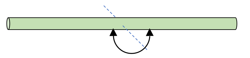
Speed of a rod as it falls
A rod of length L is free to rotate on a frictionless pin as shown, and the rod is released from rest in the horizontal position.
- What is the angular speed of the rod in its lowest position (right before it hits the wall)?
- What is the linear speed of the center of mass at this lowest position?
- What is the linear speed of the end of the rod at this lowest position?
- ω= (3g/L)^0.5
- vcm=1/2 (3g/L)^0.5
vcm=1/2 (3gL)^0.5 - vend=(3gL)^0.5
Masses connected to a pulley
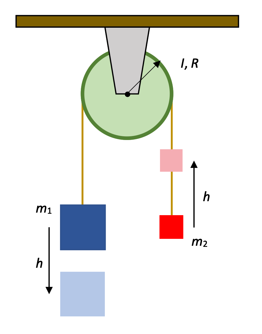
Two masses are connected to a pulley as shown and the system is released from rest.
- Find the linear speeds of the masses after m1 has descended a distance h.
- Find the angular speed of the pulley at that moment.
They've asked us to identify speeds (rather than accelerations), which leads us to think that an energy-based solution would be appropriate. The initial and final states of the masses have been clearly identified, so assuming there's no heat loss, we can just look at the potential and kinetic energies here.
There are a lot of energies to track, though!

